Categories
NexusPort-channel is a technique which is used to combine multiple physical links into a single logical link.
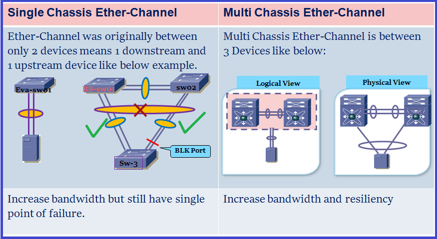
Here we are going to discuss Multi-chassis Ether-Channel.
Multi-chassis ether-channel is in between 3 devices. There are three main type of multi chassis ether-channel as below:
1. 3750/3850 – Cross stack port channels
2. VSS (in 6500 virtual switching system)
3. Nexus vPC
##Stack wise switch and VSS uses a single control plane but vPC uses two separate control plane.
Without MEC, the downstream device can have multiple links bundled together and connected to a single upstream switch. but MEC … here we discussing about vPC so vPC allows a downstream device to combine multiple physical links into a single logical link, which then connects to two different upstream switches configured in a same vPC domain.
vPC terminology:

vPC: The combined port-channel between the vPC peers and the downstream device is known as vPC.
vPC Peer: A pair of Nexus switches that is going to act as a single logical switch for downstream devices. Remember vPC works only on Nexus devices means vPC peer must be Nexus devices and downstream device can be server or switch or any other networking device that support link aggregation technology.
vPC VLAN: vPC VLAN is a VLAN that is configured on vpc peer-link and vpc port-channels means used to communicate via vPC with a other devices. As soon as a VLAN is passed over Peer-Link, it becomes a vPC VLAN.
Non-vPC VLAN: A VLAN that is not part of any vPC and not present on vPC Peer-Link.
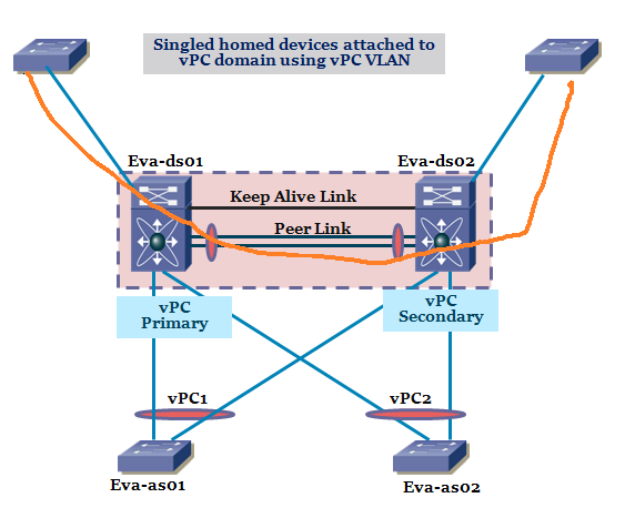
Orphan Port: Orphan Port is a port which is not part of vPC. but it should be a part of allowed VLANs on Peer-link.
single homed devices also considered as Orphan Port which should match the above statement.
Do you mean if a VLAN X which is not passed over peer-link but have a port assigned to the VLAN X will not consider as orphan port? Yes it’s not.
vPC peer Link
- vPC peer-link is a layer 2 link which is used to synchronize Control Plane information between the vPC peer devices (like mac address, vPC member state information, IGMP using CFSoE protocol). Both ends must be on 10-Gigabit Ethernet interfaces.
- Used to elect a vPC primary and vPC secondary role.
- Carry multicast/broadcast/flooding traffic and data traffic in case of vPC member port failure
- Carries STP BPDUS, HSRP Hellos, IGMP updates.
Keepalive Link
- The Keepalive link is used to monitor the aliveness of the peer device. The peer Keepalive link sends periodic keepalive messages between vPC peer devices. No data or synchronization traffic moves over the vPC peer keepalive link; the only traffic on this link is a message that indicates that the originating switch is operating and running vPC.
- Used to prevent active/active or split brian vPC roles.
- Not used in the vPC Data Plane.
- Uses unicast udp port 3200 (TTL16)
- The default interval time for the vPC peer-keepalive message is 1 second. The default timeout value is 5 seconds.
In order of preference, the following types of interface should be used for the vPC PK
link:
1. Dedicated Link (1Gbps is sufficient) using dedicated VRF
2. mgmt0 interface (shared link with management traffic)
3. Routed over L3 infrastructure (least preferred)
Cisco Fabric Services Protocol:
Cisco Fabric Services (CFS) protocol provides reliable synchronization and consistency check mechanisms between the 2 peer devices and runs on top of vPC peer-link. The protocol was first implemented on MDS products (network storage devices) and then ported to NEXUS devices. Cisco Fabric Services is enabled by default when vPC feature is turned on.
Cisco Fabric Services (CFS) protocol performs the following functions:
- Configuration validation and comparison (consistency check)
- Synchronization of MAC addresses for vPC member ports
- vPC member port status advertisement
- Spanning Tree Protocol management
- Synchronization of HSRP and IGMP snooping
- Cisco Fabric Services messages are encapsulated in standard Ethernet frames that are delivered between peers exclusively on the peer-link. Cisco Fabric Services messages are tagged with CoS = 4 for reliable communication.
vPC Member Links
vPC member links are the interfaces taking part in the port channel itself; in other words, the connections to the downstream switch.
The following recommendations apply to the vPC member links:
The configuration of the vPC member links should be identical across the two vPC peer switches in particular, the vPC ID must match across the two peers, while the Port Channel number should match across the two peers for ease of management.
vPC Domain:- vPC domain includes vPC peer devices, the vPC peer keepalive link, and all the PortChannels in the vPC connected to the downstream devices. It is also associated with the configuration mode that we use to assign vPC global parameters.
The vPC peer devices use the vPC domain id to automatically assign a unique vPC system MAC address. vPC System MAC address is used to identify the logical switch in the Network Topology.
vPC System MAC address= 00:23:04:EE:BE:<vPC domain-id hexadecimal> ; vPC system-MAC is used only with vPC attached devices and identify Logical switch(both Peer).
vPC Local MAC address: vPC local MAC address is used with single attached devices(Orphan port) and identify each peer devices and it is unique per device.
vPC Role:
There are two defined vPC role: Primary and Secondary. vPC role defines which of the two vPC peer devices processes Bridge Protocol Data Units (BPDUs) and responds to Address Resolution Protocol (ARP).
The roles are decided based on the priority(1 to 65535 and default is 32667). The lower the value is preferred if tie then uses MAC address. The initial election happens when switches join the vPC domain.
vPC operational Role: we have concept of operational role: Operational primary and operation secondary. Initially vPC role are equal to vPC operational role but can be changed during failure.
vPC role matters in Peer-link failure. vPC role is non-preemptive to prevent control plane disruptions caused by unnecessary role changes.
How to swap the vPC role if secondary becomes operation Primary:
Order of vPC Initialization:
1. vPC process/manager starts.
2. Peer-Keepalive comes up
3. Peer-link comes up
4. Primary/Secondary Role election
5. global consistency checks
6. Peer-Link is up for Data
7. SVIs moves to up/up state
8. vPC member ports moves to up/up state
Loop Avoidance Mechanism:
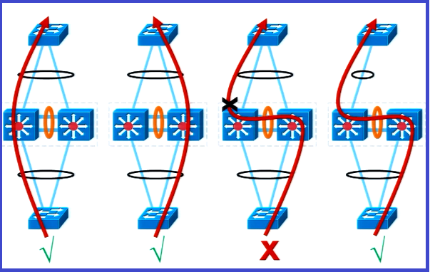
vPC has Loop prevention mechanisms where traffic/frames coming from VPC member port and crossing peer-link is not allowed to egress to any vpc member port. ( Duplicatre frame Prevention ) while remote vPC peer has active vPC members in the same vPC ; however it can be forwarded any other type of port like orphan port or L3 Port.
In Simple words, we can say if a member port receives a frame and it is forwarded across the peer-link. When the peer switch receives it on peer link, it will not forward the frame out a vPC member port.
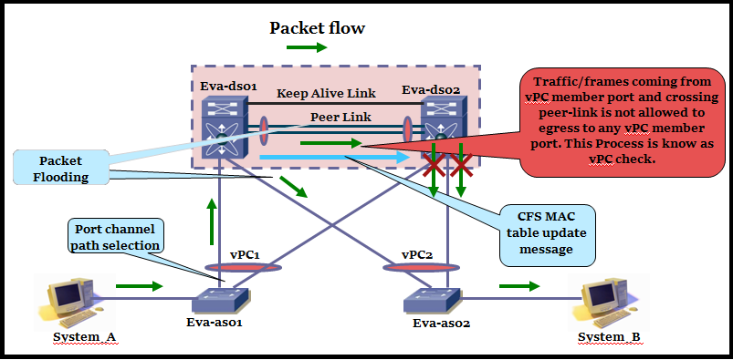
vPC check Exception: if vPC peer’s member ports are down the vPC member ports become “Orphan ports” and vPC Check is disabled. vPC check is happening per port-channel basis.
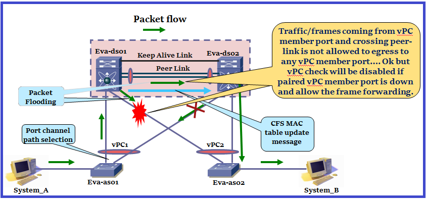
Let’s have look to better look to understand vPC checks in below diagram:
Spanning Tree in vPC domain
STP runs on both switches as we have 2 separate control planes in vPC. For vPC ports only the operational primary switch generates and process BPDUs means STP is controlled by vPC primary for peer devices.
vPC switches have to be ‘seen’ as a single switch to vPC connected devices and this happens by using the system MAC. If Secondary receives a BPDU, it will forward it across the peer-link for the primary switch to process. Port state changes are communicated to secondary via CFS messages.
For non-vPC Ports domain appears as 2 bridges means non-vPC Ports are managed independently by Local STP process on each switch.
** vPC Peer-link is a regular port for STP. vPC makes sure that Peer-Link is always forwarding. in fact if the switch has a direct path to root, the secondary vPC peer switch always sees the peer link as root port towards the primary vPC devices.
vPC “Peer Switch” feature:
This feature allows, both vPC primary and secondary switches to originate same STP BPDU on vPC Port and use the same bridge id using vPC system MAC address and whenever we enable peer-switch , it is mandatory that both devices have the exact same spanning tree priority.
This feature allows to keep the same BPDUs when primary fails/recovers– > no extra sync required means there will not be any interruption in forwarding.
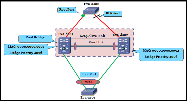
Both switch (Eva-ds01, Eva-ds02) are configured with same priority for all VLANs. Eva-ds01 wins bridge election because it has the lower bridge id. therefore you expect Eva-as02 to block on the link from Eva-ds02. Eva-as01 is connected to Eva-ds01 & Eva-ds02 via a vPC and will be in forwarding state. Eva-as01 receives BPDUs only from primary switch in vPC which is Eva-ds01 in this example.
Before starting Peer-switch we have to understand, STP behaviour when vPC Primary fails completely: when vPC Primary fails then secondary will become operational primary and STP Root. From STP point of view there is no change in RP and No STP port state changes for vPC so traffic forwarding will be continuous. Once secondary become operational it starts sending BPDUs depending on Control plane load.
Now think like Primary came up after a while, it will take role as primary but operational will be secondary. As we know primary which is now operational secondary has better bridge id so it will become STP Root. once Primary (operational secondary) become STP Root then STP root port of secondary(operational primary) will change and that will trigger “Sync” Process and all non-edge ports will be in temporarily blocked. Once “Sync” is completed ports will resume the forwarding. To overcome this situation we use Peer-Switch”.
Same example with Peer-switch Enabled: (Non-vPC connection)
vPC Primary and secondary generates BPDUs with root bridge id set to virtual bridge id and designated bridge set to physical bridge id. In our diagram Eva-as02 will block one link which is connected to Eva-ds02 ( Higher Physical Bridge id).
Peer-switch is enabled in vPC connection:
vPC connection receive BPDUs with both root bridge id and Designated bridge id set to the virtual bridge id.
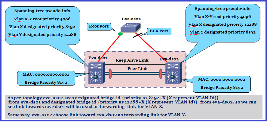
Enable Load Balancing between VLANs over Non-vPC links:
Under default Peer-switch configuration all VLANs on the non-vPC switch are forwarding on single link. In order to load balance between VLANs, designated and root priorities can be manually set by using “spanning-tree pseudo-information” configuration.
Cisco recommends that root priority under the “psedo-information” be lower than best spanning-tree priority in order to prevent topology change notification under failover conditions.
Let’s have look in below topology:
HSRP with vPC:
HSRP work as below:
Control Plane: Active/standby
Data Plane: Active/Active

User will send the ARP for it’s gateway. HSRP will reply with virtual MAC address. User creates an Ethernet frame with destination address of virtual MAC address.Once frame reaches at Eva-as01, Eva-as01 will use it’s etherchannel load balancing algo to determine the physical link to use. The difference is now that it doesn’t matter which link it uses even if packet reaches to standby, standby will accept and route the packet. in effect switches are HSRP active at the same time.
Peer-Gateway:
The “vpc peer-gateway” allows HSRP routers to accept frames destined for their vPC peers.
**why we need this: to allow vPC interoperability with some network-attached storage (NAS) or load-balancer devices that do not perform a typical default gateway ARP request at boot up.
As NAS device don’t perform standard ARP request to retrieve MAC address of the default gateway, it uses an another method to learn this MAC address. This can be done by listening to the network traffic and selecting the first received source MAC ddress as default gateway MAC address.
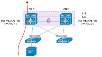
Let’s assume NAS device receives its first packet from vPC peer device 7K2. In this case, it will use MAC address of interface VLAN 10 on 7K2 as default gateway MAC address. All routed traffic sent by NAS device need then to reach 7K2 in order to be routed correctly (L3 traffic destined out of vPC domain or inter-VLAN traffic). For inter-VLAN traffic, there is a risk to hit the vPC loop avoidance issue: NAS device send routed traffic, access switch hashes the traffic in direction to 7K1; 7K1 has to bridge the traffic over vPC peer-link because 7K2 MAC address (more exactly MAC address of interface VLAN 10) is the L2 destination of this traffic.
Now, if traffic needs to exit out a vPC member port, it will be dropped in hardware because of vPC loop avoidance rule. By enabling vPC Peer-Gateway functionality, each vPC peer device will replicate locally MAC address of interface VLAN defined on the other vPC peer device with the G flag (Gateway flag). In the above figure, 7K1 will program MAC2 (MAC address of interface VLAN 10) in its MAC table and set G flag for this MAC address. 7K2 will do the same for MAC1.
Step for vPC implementation
1. Enabling the feature:- we need to activate the vPC and LACP feature in order to
build a proper vPC configuration.
2. Peer Keepalive connectivity: The Peer Keepalive link is used to detect failure
between the peers. It is definitely not used in the data plane.
3. vPC domain
4. vPC peer link configuration
5. Establish port channel for vpc peer link
6. Verify vPC consistency parameters.
7. Configure vPC Member Ports.
8. Enable vPC member Ports on Primary.
9. Enable vPC Member Ports on Secondary
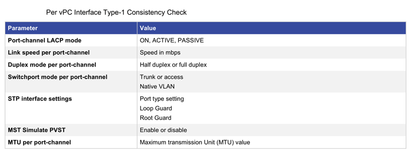
When a mismatch in Type 1 parameters occur, the following applies:
- If a graceful consistency check is enabled (default), the primary switch keeps the vPC up while the secondary switch brings it down.
- If a graceful consistency check is disabled, both peer switches suspend VLANs on the vPC ports.
There are two type of type 1 consistency as below:
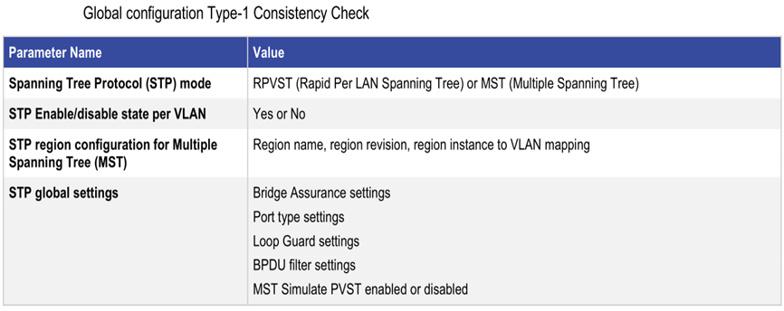
IF there is type 1 global configuration inconsistency detectected then all vPC member ports on secondary peer are set to down state.If there is type-1 interface inconsistency detected then only the inconsistent vPC member ports on secondary peer device are set to down state.
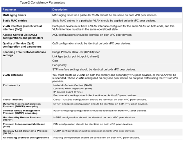
When Type 2 parameters exist, a configuration mismatch generates a warning syslog message.
| Peer device 1 | Peer device 2 |
| feature vpc | feature vpc |
| vrf context Keep_Alive | vrf context Keep_Alive |
| ! | ! |
| default interface EX/Y | default interface EX/Y |
| interface EX/Y | interface EX/Y |
| vrf member Keep_Alive | vrf member Keep_Alive |
| ip address 192.168.1.1/30 | ip address 192.168.1.2/30 |
| no shutdown | no shutdown |
| ! | ! |
| vpc domain 10 | vpc domain 10 |
| role priority 1 | role priority 2 |
| peer-keepalive destination 192.168.1.2
source 192.168.1.1 vrf Keep_Alive |
peer-keepalive destination 192.168.1.1 source
192.168.1.2 vrf Keep_Alive |
| peer-switch | peer-switch |
| peer-gateway | peer-gateway |
| auto-recovery | auto-recovery |
| ip arp synchronize | ip arp synchronize |
| ! | ! |
| interface poX | interface poX |
| vpc peer-link | vpc peer-link |
| ! | ! |
| interface port-channel 6 (gateway port-channel config) |
| vpc 6 |
| Downstream switch config (Normal Portchannel config) |
| interface Eth1/1-2 |
| channel-group 1 mode active |
While doing config we careful check keep-alive config, connectivity and consistency
parameter is proper using below show commands.
show vpc
show vpc role
show vpc consistency-parameters global
show vpc consistency-parameters interface po1111
show vpc peer-keepalive
show vpc orphan ports
vPC failure Scenario:
As we know, In vPC there are two device that are the vPC peer, one is primary and one is secondary. vPC peer device has separate control plane so problem we can ran into is split brain or active/active type of situation where control plane is broken between vPC peer and both vPC peer assume vPC primary role. Peer Keepalive and Peer Link have built in protection against Active/Active situation.
Case-1: Failure reaction when vPC Peer Link fails:

If Peer Link fails first and then complete failure of vPC primary. In this case secondary kept its all vPC member Port in suspended because secondary is not continuously checking for vPC primary is available or not because of this both vPC primary and secondary are disabled.
We can overcome from this situation using “auto recovery” feature which is disable by default. vPC auto recovery allows vPC secondary to assume Primary in certain failure situation:
A. When vPC Peer Link goes down then it checks active status of remote vPC Peer via vPC Keepalive Link.
B. If both Peers are active then secondary vPC will disable all its vPC Member ports and SVIs.
C. If primary completely fails than secondary doesn’t re-enable suspended ports
D. If “auto recovery” is enabled then vPC secondary actively checks for keepalive and in case keepalive fails then vPC secondary promotes itself to Primary and un-suspends vPC member Ports.
Second case where auto recovery can play important role:
A. Power outage occurs on both primary and secondary.
B. After boot if vPC peer link doesn’t come up, role election can’t occur and vPC never comes up.
C. But if “auto recovery” is enabled then auto recovery allows a single vPC Peer to elect itself as vPC Primary after configured timeout if vPC link is not coming up after reload means vPCs are brought up bypassing consistency checks.
Problem with Auto Recovery:
If Link cut on both Peer Link and Keepalive and auto recovery is enabled means Secondary will elect itself as Primary means Dual Primary. Traffic forwarding fails for new flow.
vPC Orphan Ports Suspend:
As we discussed, whenever the vPC link goes down the vPC secondary will disable all it’s member ports and shutdown the SVI associated to the vPC VLAN, assuming vPCs are up in the vPC primary (as Keepalive is live).
Orphan ports are left as up and traffic can be blackhole depending on our topology.
So if we want to configure secondary to bring orphan port down on this situation then we will use “vPC orphan-port suspend” command under interface level.
When we can’t dual-attach the devices to a vPC domain, there are two main alternatives are available:

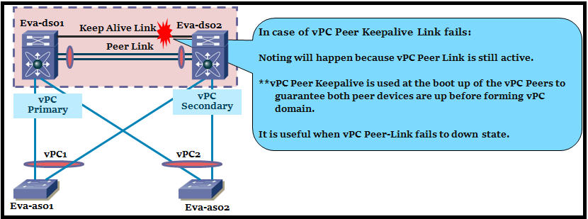
Case-2: Failure Reaction when vPC Peer Keepalive Link fails:
Case-3: Failure Reaction when VPC keepalive link fails followed by a peer link:

Video
Really Helpful, Keep going… Lot more to come…
Thank you!
As always very helfpul information.
This is just awesome boss…
Clear & precise information.
Good content. Some diagrams dont have explanations, but yes overall content is really good. Keep up the good work !
very clear information. Thanks a lot!!