Categories
SwitchingRSTP
Rapid Spanning Tree Protocol (RSTP) is defined in standard IEEE 802.1w.
RSTP has a much faster convergence than 802.1d due to the following features:
- RSTP is not using a timer-based algorithm like traditional STP, and uses regular BPDU’s sent at every hello time interval as a form of keepalive.
- In STP we have to enable uplink fast and backbone fast to detect direct and indirect failure but RSTP have inbuilt functionality (because it maintains backup and alternate port).
- RSTP uses a new, improved topology change mechanisms, which leads to faster change detection and propagation.
Port roles
- Root port – A forwarding port that is the best port from Non-RB to RB.
- Designated port– A forwarding port is elected for every LAN segment.
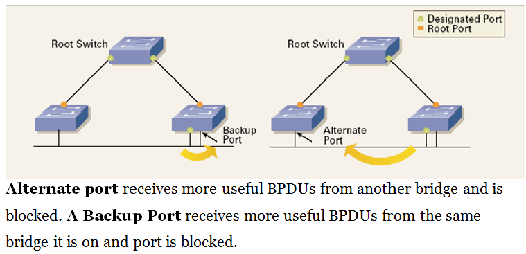
- Alternate port– Backup of root port. Alternate path to the root bridge.
- Backup port– Backup of designated port. Remember one thing Backup Port applies only when a single switch has two links to the same segment or collision domain. To have two links to the same collision domain the switch must be connected to a hub.
Port states
- Discarding state–No mac address is learned, no frames is sent or received, only BPDU is exchanged.
- Learning state –Learn mac address, no data frames is received or sent. BPDU is exchanged.
- Forwarding state– Learn mac address, data frames is sent and received. BPDU is exchanged.
Convergence with RSTP
802.1w RSTP convergence is fast due to a new proposal/agreement mechanism, which does not rely on timers like 802.1d.
All Non-Edge ports will initially be Designated/Discarding state & proposals are sent. Whenever port comes up between switches, both port will negotiate on link type (Point to point or shared) and Port role and state.
By default whenever link comes up the port role is designated and state is discarding. So it starts considering itself as the root bridge.by default it will put its non-edge ports into designated/discarding (role/state) and start sending BPDUs with Proposal bit set.
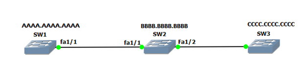
- When sw-1 receives BPDU of sw-2, sw-1 will compare its bridge id with sw-2 and will ignore the sw-2’s BPDU. On the other hand , sw2 will accept the SW1’s proposal (as superior) and sends a BPDU with agreement bit set and Before sending Agreement BPDU sw-2’s port will set to root/discarding state.
- During the Proposal/Agreement handshake, these switches also start their sync process where switch put all the Non-Edge designated port into designated/discarding state.
- When sw1 receives Agreement BPDU, it will immediately transit it’s port from designated/discarding to designated/forwarding and switch-2 will transit its port from Root/Discarding to Root/Forwarding.
- Same process will happen between Sw2 and Sw3. SW2 will ignore SW3’s BPDU (being inferior) and continues to send BPDU saying SW1 is the root with proposal bit set. SW3 on the other hand will accept the superior BPDU, put SW3 Fa1/1 to Root/Discarding and sends BPDU with agreement bit set.
What happen if we connect new switch in existing RSTP domain?
When switch comes up in your domain, it starts considering itself as Root Bridge and by default put its non-edge ports into designated/Discarding and start sending Proposals. However if its Bridge-id is higher than current root, it will not become a new root switch and these proposals will be unanswered and will do normal process and choose it’s Root port.
New Topology Change Detection and Propagation
In RSTP, a topology change occurs only if non-edge ports move to a forwarding state. Topology change (TC) in 802.1w differs from 802.1d to reduce the flooding of data.
In 802.1d, the TCN was unicasted to the root bridge and then multicasted to all bridges. The receipt of an 802.1d TCN causes a bridge to fast age all entries in the forwarding table irrespective of whether the bridges forwarding topology was affected.
RSTP, by contrast, optimises this operation by explicitly telling the bridge to flush all entries except those entries that were learned via the port on which the TC was received. This change in TC behaviour significantly reduces the amount of MAC addresses flushed during a topology change.
You have to think like below:
“What CAM entries in my switch will be cleared upon receipt of a Topology Change?”…just remember:
- TCs are forwarded out Root and Designated Ports.
- Clear any CAM entries related to ports where you FORWARDED THE TC (except Edge Ports)
- Do NOT clear entries for ports that RECEIVED THE TC.
Let’s go through the example, when an RSTP bridge detects a topology change, it performs these actions:
- It starts the TC While timer with a value equal totwice the hello-time for all itsnon-edge designated ports and its root port, if necessary.
- It flushes the MAC addresses associated with all these ports.
- As long as the TC While timer runs on a port, the BPDUs sent out of that port have the TC bit set. BPDUs are also sent on the root port while the timer is active.
Topology Change Propagation
When a bridge receives a BPDU with the TC bit set from a neighbor, these occur:
- It clears the MAC addresses learned on all its ports,except the one that receives the topology change.
- It starts the TC While timer and sends BPDUs with TC set on all its designated ports and root port (RSTP no longer uses the specific TCN BPDU,unless a legacy bridge needs to be notified).
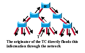
This way, the TC floods very quickly across the whole network. The TC propagation is now a one step process.
In fact, the initiator of the topology change floods this information throughout the network, as opposed to 802.1D where only the root did.
This mechanism is much faster than the 802.1D equivalent. There is no need to wait for the root bridge to be notified and then maintain the topology change state for the whole network for <max age plus forward delay> seconds.
What happened if new switch is added in existing environment?
Let’s have an example: In our topology sw1 is acting as Root Bridge and we have added new sw4 in existing environment with lower bridge id.
Type of STP
STP:
Standardized as IEEE 802.1D. Single Spanning Tree instance for Entire L2 Network regardless of number of VLANs.This implementation reduces CPU load since only one Spanning Tree instance is maintained for the entire network.All CST BPDUs are sent over trunks using the native VLAN with untagged frames means cannot differentiate between different VLANs, therefore support natively only one single instance of STP for all VLAN.
PVST (Per-VLAN Spanning Tree) :
Cisco Proprietary Protocol. PVST maintains a spanning tree instance for each VLAN configured in the network that allows the STP on each VLAN to be configured independently and if configuring individually means we can achieve load balancing traffic at L2 by passing some VLANs on one trunk and other VLANs on another trunk without causing a Spanning Tree loop. It uses ISL Trunking that’s by not compatible with CST.
PVST+ : Cisco Proprietary
Per VLAN Spanning Tree Plus (PVST+) provides the same functionality as PVST using 802.1Q trunking technology rather than ISL.
As we know CST run only one instance for all VLAN but PVST runs STP instance for each VLAN means if we have 10vlan then there will be 10 STP instances.
If the native VLAN is VLAN1 then:
- CST sends untagged STP BPDUs to STP Multicast Address (0180:c200:0000). These BPDUs are processed by VLAN 1 on Cisco switches.
- Cisco switch sends untagged IEEE STP BPDUs to STP multicast address for VLAN 1. At the same time, special new SSTP (shared spanning tree) BPDUs are being sent to SSTP multicast MAC address “0100.0ccc.cccd” also untagged. These SSTP BPDUs are encapsulated using IEEE 802.2 LLC SNAP header (SSAP=DSAP=”0xAA” and SNAP PID=”0x010B”). These BPDUs carry the same information as the parallel IEEE STP BPDUs for VLAN 1, but have additional fields, notably a special TLV with the source VLAN number.
- As for non-native VLANs) Cisco switch sends only SSTP BPDUs, tagged with respective VLAN number and destined to the SSTP MAC address.
If the native VLAN is different from VLAN1(default) then:
- CST sends untagged STP BPDUs to STP Multicast Address (0180:c200:0000). These BPDUs are processed by VLAN 1 STP instance on Cisco switches.
- Cisco switch sends untagged IEEE STP BPDUs to STP multicast address for VLAN 1.This is done for the purpose of joining the local VLAN 1 instance and the IEEE instance into CST. At the same time, VLAN 1 BPDUs are replicated to SSTP multicast address, tagged with VLAN 1 number (to inform other Cisco switches that VLAN 1 is non-native on our switch).
- BPDUs of the native VLAN instance (VLAN X) are sent untagged using SSTP encapsulation and destination address. Native VLAN X BPDUs carry VLAN number inside a special TLV SSTP header even though they are untagged.
- As for non-native VLANs) Cisco switch sends only SSTP BPDUs, tagged with respective VLAN number and destined to the SSTP MAC address.
Note:
If you are running spanning-tree mode PVST then the PVST or PVST+ will be automatically run on trunks according to theirencapsulation.ISL trunks will run PVST while IEEE 802.1Q trunks will run PVST+. There is no special command to activate only PVST or only PVST+.
RSTP(Rapid Spanning Tree Protocol):-
Standardized as IEEE 802.1w. RSTP is an evolution of the Spanning Tree Protocol (802.1D standard) and provides for faster spanning tree convergence after a topology change.The standard also includes features equivalent to Cisco UplinkFast and BackboneFast for faster network re convergence.
Comparision between STP and RSTP:
- In STP only Root Bridge only can send bpdu (configuration BPDU) but RSTP Introduce proposal and agreement process for synchronization and all switch participate in Sync process.
- In STP we have to enable uplink fast and backbone fast to detect direct and indirect failure but RSTP have inbuildfuncitionality (because it maintains backup and alternate port).
- Different Port Roles and different Port States.
RPVST+:- Cisco Proprietary
Is basically mix the RSTP and PVST+.
MST :
1. Multiple spanning tree is standardlieed as 802.1s
why we need MST ?
Prior to giving answer, i would like you to recall different STP types and limitation as below:
1. As we know in CST, we have single spanning tree instance for enter L2 N/W regardless to number of VLANSs . This implementation reduces CPU load as we have single spanning tree instance for entire N/W but load balancing can not be achieved . CST does not exist in Cisco Platforms.
2. PVST / PVST +/RPVST/ : As we know in PVST/PVST+, we have X VLAN = X Instance[ X= number of vlan ] which allow flexible load balancing by manipulating spanning-tree Instances But CPU needs to handle X number of instances even if we have few (two or three) different topology . or we can think like if we have 10 VLANs means 10 separate BPDUs will either be sending or receiving in every two second .
3. MST
A. flexible load balancing
B. Reduces CPU load as we have mapped group of VLANs to one instance .
Let’s start MST for better understanding
Region = MST region is a group of switches under the same administrative control and have same configuration .
MST region have following attribute which have to match .
1. Configuration Name: 32 bits and case sensitive
2. Configuration revision number: 16 bit
3. VLAN to instance mapping
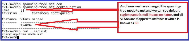
As soon as we configure spanning tree mode as MST then it will take default region name as “Null” basically means no name . By default MST creates Instance 0 and all VLANSs are mapped to instance 0 .
Remember instance 0 is special instance which is known as IST. other instance configured by us (like 1,2,N) are known as MSTIs .
Let’s discuss about IST:
1. IST is the only instance that can send and receive BPDUs in the MST region. Information related to other Instance (like 1,2,N) which is known as MSTI are contained in the M-Record.
2. IST presents MST region as one single virtual bridge to the outside n/w.
3. IST is instance 0 in MST and it always exist on all the ports and can’t be deleted.
4. Hello, forward delay and max-age can only be set for the IST.
M-Record :
Mrecords contains information that give us all information which we need to calculate spanning tree for particular instance.