Categories
SwitchingAgenda
- What is port-channel or EtherChannel?
- How we create Port-channel and how it work?
- Why we create Port-channel?
- Practical where we see mismatch can be major issue?
- Why Negotiation is always better choice?
- Port-channel is a technique which is used to combine multiple physical links into a single logical link.
- Traffic that is switched or routed to port channel interface is load balanced between member links through hashing mechanism.
- Advantage of Port-channel:
- Increases the available bandwidth between two devices.
- Creates one logical link by combining multiple physical links, so now STP runs on port-channel interface not on physical link so all of the physical port will be forwarding state and can forward traffic.
- When any member link fails Port-channel will automatically redistribute traffic across the remaining links. This automatic recovery is transparent to network applications and the end user.
- Remember one thing “single flow can’t exceed bandwidth of any physical member linkbut aggregate of all flows can consume aggregate of port-channel bandwidth.
Take an example below to understand above statement:
Let’s say we have two switches connected together with 4*10 GB link, and we put them into a port channel, now our bandwidth is 40 GB but our max throughput is still 10 GB for single flow. Why?
When a switch is sending frames across a port channel it has to use some sort of algorithm to determine which physical link to send the frames on. Since all frames (for specific flow) between sender and receiver will always be on the same 10 GB link that results in a maximum throughput of only 10GB. Another Flow can choose another link. Means if four flows using 4 different link from port-channel means aggregate of all 4 flows can consume the aggregate of port-channel interface bandwidth which is 40GB. Again do remember one thing all this story depends on load balancing algorithm.
5. Etherchannel consist two parts:
- Port-channel Interface: Logical interface which represent link bundle
- Member Link: – Physical interface which is in Link bundle or in port-channel
6. Port-channel can be configured as a layer 2 or layer 3.
7. There are two protocols used for the link aggregation:
PAgP: – it’s Cisco’s proprietary Port Aggregation Protocol (PAgP).
LACP: – it’s open standard Link Aggregation Protocol (LACP)
| Negotiation mode | Description | |
| PAgP | LACP | |
| Auto | Passive | interface will wait passively for the other side to ask to become Port-channel |
| Desirable | Active | Interface will actively ask the other side to become Port-channel means sends LACP or PAgP to negotiate with other end. |
| On | On | Ether-channel is forced to be formed without using any PAgP/LACP negotiation. |
Something about LACP:
8. Recommended way to create Layer 2 Port-channel:
A. Check all physical port which is going to participate in port-channel should have identical configuration
or
Default the interfaces which are going to participate in port-channel.
B. Assign “channel-group” to physical interface which will automatically create port-channel interface. While using channel-group command make sure that channel-group number is not already in use.
Channel-group number is locally significant to device but we generally use same at both end of ease management.
C. Reset the physical and logical interface using “shut than no shut” command.
D. Configure trunking encapsulation or other configuration like addition and removal directly under port-channel interface.
9.Load Balancing:
Traffic is not randomly placed across the member ports but instead shared using some sort of hash algorithm. Etherchannel load balancing can use L2/L3/L4 header information as source or destination or both to decide egress port of Port-channel to transmit packet.
Load balancing method can be below:
- SRC-MAC 2. SRC-DST-MAC 3. DST-MAC 4. SRC-IP
- SRC-DST-IP 6. DST-IP 7. SRC-Port 8. DST-Port 9. SRC-DST-Port.
Load balancing operates at switch level rather than per port-channel.
eva-sw1(config)#port-channel load-balance (select_your_Method)
I tested couple of mismatches to see what will happen in below topology. You may think it’s useless but it will help you to troubleshoot in live environment.
1. When we configured Port-channel at both end (Eva-sw1 and Eva-sw2). Port channel came up means port is in Bundled mode. Bundled (In use) mode means port is part of an Etherchannel and can send and receive BPDUs and data traffi.
Please find the below output.
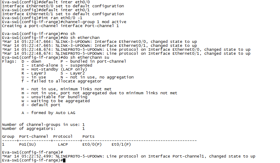
| Eva-sw1#sh run int eth0/0
Building configuration… Current configuration : 58 bytes ! interface Ethernet0/0 channel-group 1 mode active end Eva-sw1#sh run int eth0/1 Building configuration… Current configuration : 58 bytes ! interface Ethernet0/1 channel-group 1 mode active end Eva-sw1#sh run int po1 Building configuration… Current configuration : 31 bytes ! interface Port-channel1 end Eva-sw1# |
Eva-sw2#sh run int eth0/0
Building configuration… Current configuration : 58 bytes ! interface Ethernet0/0 channel-group 1 mode active end Eva-sw2#sh run int eth0/1 Building configuration… Current configuration : 58 bytes ! interface Ethernet0/1 channel-group 1 mode active end Eva-sw2#sh run int po1 Building configuration… Current configuration : 31 bytes ! interface Port-channel1 end Eva-sw2# |
2. Now as port-channel is up and running. I changed encapsulation type on one physical interface and found port is going in suspended state. Let’s see this in below output.
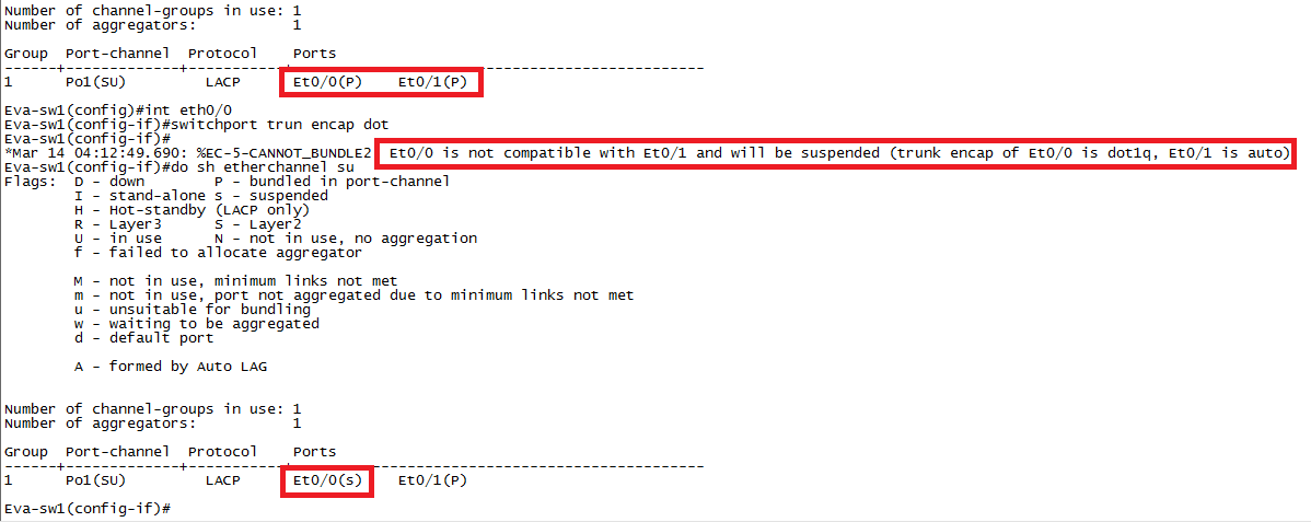
Best way: if you want to configure trunking encapsulation/other configuration like VLAN addition or removal than configure it directly under port-channel interface. Like below:
| Eva-sw1#sh run int po1
Building configuration… Current configuration : 162 bytes ! interface Port-channel1 switchport trunk allowed vlan 10,20 switchport trunk encapsulation dot1q switchport trunk native vlan 10 switchport mode trunk end Eva-sw1# |
Eva-sw2(config)#do sh run int po1
Building configuration… Current configuration : 162 bytes ! interface Port-channel1 switchport trunk allowed vlan 10,20 switchport trunk encapsulation dot1q switchport trunk native vlan 10 switchport mode trunk end Eva-sw2(config)# |
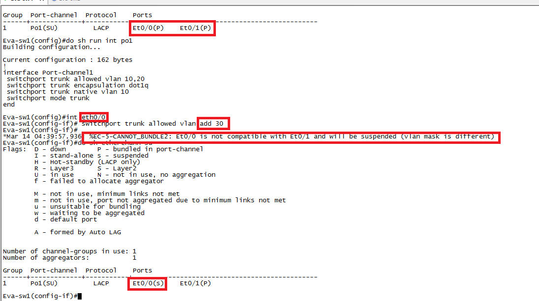
3. Added new VLAN at physical port rather than port-channel interface noticed that port went into suspended state so be careful while allowing/removing a VLAN. If we need to add or remove VLAN to/from port-channel, we have to add or remove under port-channel interface it will be automatically added or removed on physical ports. Don’t add or remove VLAN under physical interface of port-channel. If we do then VLAN on physical port will mismatch with VLAN on port-channel interface, which set physical port into suspend stage.
4. The speed/duplex must be the same, but does not need to be set via the same method on all links. I mean let’s say one port is hard coded with speed command and another port on same port-channel is configured speed auto but both working in 100 than it will not impact to your port-channel. Port-channel will work fine until your speed/duplex is identical method doesn’t matter (auto or hard code) until they are identical or same.
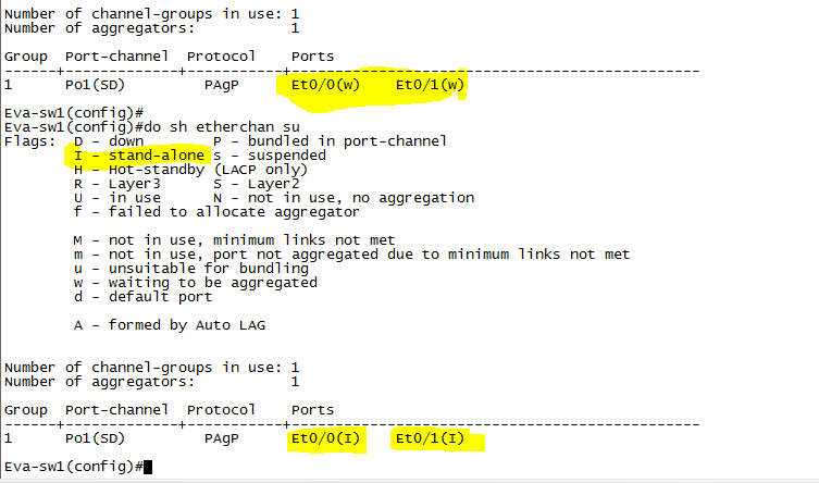
5. If configure both side as auto/auto or passive/passive means both switch will waiting to other end to ask to become port-channel but both will not ask and port channel will be in waiting state. I did “show etherchannel summary” later then came to know port moves to Stand-alone mode. Stand-alone mode means port is not bundled in an Etherchannel. The port can send and receive BPDUs and data traffic. This kind of situation comes when other end of port is not configured in etherchannel. See both output as below:
Hope you enjoyed this
One question and explanation:
Qes: What do you feel about “static port-channel”? How does loop can be form in case of misconfiguration of etherchannel?
Ans: As we know PAgP and LACP is protocol which allows dynamic negotiation of Port-channel. These protocols have management function that checks the parameter consistency at either end of link.
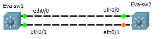
Topology:
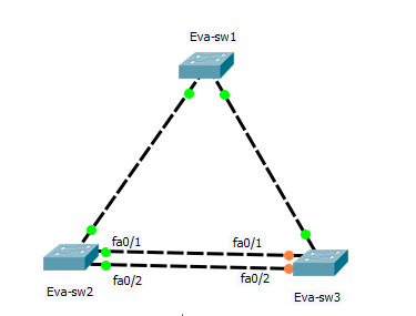
Let’s assume Eva-sw2 has been bundled in port-channel using “On” means we not using PAgp or LACP and Eva-sw3 is not configured in port-channel yet means independent link at Eva-sw3.
In this case STP act differently. Let’s have a look:
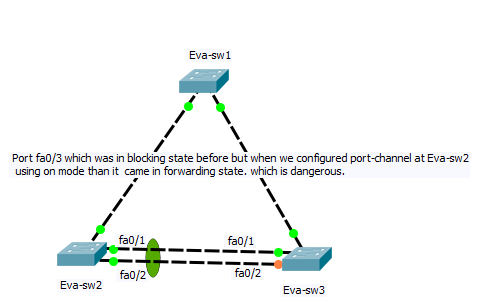
Port-channel at Eva-sw2 is treated as single port means BPDUs will be sent over the port-channel regardless of physical ports are bundled in port-channel. At Eva-sw3, after some time BLK port will become DP and starts sending BPDUs which will create loops.
In case of RSTP and MST this can be avoided by Dispute mechanism.
Please find below link for more info:
STP_RSTP_Dispute mechanism
Something about LACP:
LACP is protocol which allows dynamic negotiation of Port-channel. These protocols have management function that checks the parameter consistency at either end of link means basically ensuring that links are only bundled (Port-channel) if they are consistently configured and cabled. LACP (Link Aggregation Control Protocol) is defined as IEEE802.3ad.
LACP Parameters
There are several LACP parameters that are contained in the LACP PDUs that are exchanged between switches. LACP uses the following parameters;
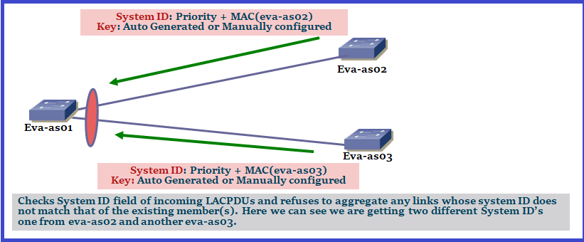
- LACP system ID: The LACP system ID is the combination of the LACP system priority value and the MAC address. The system ID is sent within every LACPDU and ensure that we are making port-channel to expected device.
- LACP port priority: Each port in the switch have a Port-ID. Port Identifier is the combination of port priority and the port number. The switch determine the Port Priority automatically or through manual configuration. LACP uses the port priority to decide which ports should be put into standby mode when there is a hardware limitation that prevents all compatible ports from aggregating.
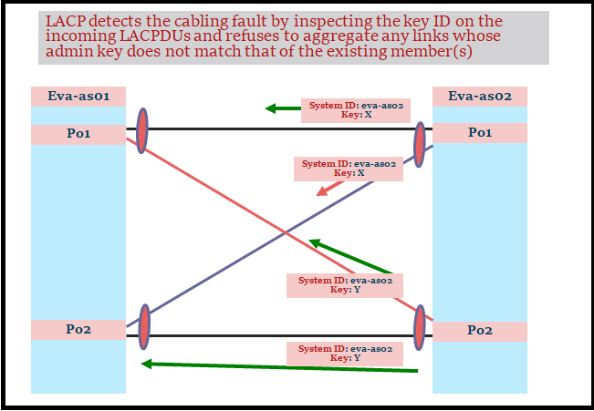
- Administrative Key: LACP automatically configures an administrative key value on each port configured to use LACP. The administrative key defines the ability of a port to aggregate with other ports. Only ports that have the same administrative key are allowed to be aggregated into the same port channel group. A port’s ability to aggregate with other ports is determined by physical characteristics, such as data rate, duplex capability, and point-to-point or shared medium, or by administrator-defined configuration restrictions or constraints.
Let’s take an example: SW1 has a system priority 32768 (default) and SW2 has a priority of 32766, SW2 will become the decision maker since it has the lowest system priority. SW1 and SW2 has ports 1 -9, configured in ether-channel. The decision maker (SW2), the switch with the lowest priority, picks which eight of nine ports are active. The ports are picked based on lowest port priority and if port priority tie then the lowest port number wins and the other is set to stand by.
Here we have Diagram to have a closer Look to understand LACP Parameter:
Awesome explanation.
Awesome document.. thanks