Categories
SwitchingAgenda
- Basic Function of switch and switching method.
- Introduction of LAN and VLAN
- Why we create VLAN?
- Type of Layer 2 switchport
- What is Trunking and Type of trunking Protocol?
- Introduction of DTP
- Introduction of Native VLAN
- Inter-VLAN Routing
- Practical scenario
- What is Private VLAN and how to configure Private VLAN?
Switch function at Layer 2:
1. Address Learning: Learning is a process to build MAC address table of connected devices. MAC address is learnt from source MAC address of received frame. When switch receives a frame on switchport, switch will read the MAC address of source device from received frame and will add the MAC address to the MAC address table with the associated port number.
2. Frame Forwarding or Filtering: Forwarding is a process of passing frame from one port to another port based on MAC address Table.
A. If destination MAC address is known and destination is in different segment or segment or collision domain then switch do frame forwarding to corresponding port.
B. If destination MAC address is known but destinationis in same segment then switch do frame filtering.
C. If destination MAC is Unknown means not available in MAC Address table then frame will be forwarded to all ports except Source Port. This is also known as flooding.
3. Prevent Layer 2 loops using STP
Let’s have look on frame delivery in same Network.
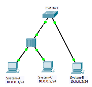
Communication between system-A and system-B in above topology:
1. System-A lookup’s for System-B MAC address in its ARP table.
A. If MAC address is not available in ARP table then System-A will send ARP Request for MAC address of System-B and sends packet to Eva-sw1.
B. Eva-sw1 will receive ARP request packet and learns MAC address of System-A and update its MAC Address table with MAC address of System-A and associated Port number.This process known as learning.
2. After that, switch will broadcast ARP Request packet in network means all devices in network/Broadcast domain receive ARP Request packet and System-B will reply with its MAC Address as System-B is owning the requested IP.
3. Eva-sw1 will receive ARP Reply packet and learn the MAC address of System-B and update the MAC address Table with MAC address of System-B and associated port number. This is again learning process for System-B MAC address.
4. Eva-sw1 will check for destination MAC Address and compare it with its MAC address table. This time Eva-sw1 knows destination MAC address and port number so Eva-sw1 will forward packet to particular port means unicast. This process is known as forwarding.
5. System-A will receive ARP Reply and add MAC address to its ARP table. Then System-A forms complete data packet and sends it to Eva-sw1. Eva-sw1 knows destination so will forward packet on associated port.
Note1.
Let’s assume we have ARP entry at System-A but the Sw1 doesn’t have Destination MAC address in MAC address Table then packet will be flooded to all port except the port on which the frame originated.
Note2.
Let’s assume destination is known and connected to same collision domain then eva-sw1 does filtering means other segments or collision domain is not get affected to it. In our diagram you can think about filtering when we are communicating from System-A to System-C.
Switching Mode:
1. Cut-Through Switching Mode
Switches operating in cut-through switching mode start forwarding the frame as soon as the switch has read the destination details in the packet header. A switch in cut-through mode forwards the data before it has completed receiving the entire frame.The switching speed in cut-through mode is faster than the switching speed in store-and-forward switching mode.
2. Store-and-Forward Switching Mode
When store-and-forward switching is enabled, the switch checks each frame for cyclic redundancy check (CRC) errors before forwarding them to the network. Each frame is stored until the entire frame has been Received and checked. Because it waits to forward the frame until the entire frame has been received and checked, the switching speed in store-and forward switching mode is slower than the switching speed in cut-through switching mode.
3. Fragment-free:
The switches operating in cut-through switching read only up to the destination MAC address field in the Ethernet frame before making a switching decision. The switches operating in fragment-free switching read at least 64 bytes of the Ethernet frame before switching it to avoid forwarding Ethernet runt frames (Ethernet frames
smaller than 64 bytes). Default switching mode is dependent on switch model. To set switching mode at switch we can use below command:
Eva-sw1(config)# switching-mode store-forward or as you requirement?
LAN (Local Area Network): A LAN is a group of devices (end user devices and network devices) connected together in the same broadcast domain.
By default, all ports on a switch are in the same broadcast domain. LANs may be found in homes, offices, educational institution, or other areas.

VLAN (Virtual Local Area Network)
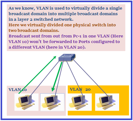
1. A VLAN is a logical grouping of devices connected together in same broadcast domain regardless to the physical location of users. VLAN is used to virtually divide a single broadcast domain into multiple broadcast domains in a layer 2 switched network.
A VLAN = A Broadcast domain = A Subnet
2. Switch has a separate MAC Address Table for each VLAN. Traffic for each VLAN is kept separate from other VLANs.
3. Broadcast Domain: Think like Broadcast + Domain –> Broadcast means one to all and Domain means logical boundary or group of ports/devices. When a device send broadcast packet in that group, it will be received by each and every device in that domain or group of device.
Having a smaller broadcast domain can improve network Performance and improve against security attacks.
4. VLAN Port Membership Mode:
1. Static VLANs:Ports on a switch are assigned to a VLAN manually. Static VLANs are also called port-based VLANs. End-user devices become the members of VLAN based on the physical switch port to which they are connected. Each port receives a port VLAN Id (PVID) that is associates it with VLAN number.
How to create VLAN and how to assign port to VLAN
Eva-sw1(config)# vlan X (X defines VLAN number)
Eva-sw1(config-vlan)# name HR
Eva-sw1(config-vlan)#exit
Adding interface to VLAN
Eva-sw1(config)#interface EthX/Y
Eva-sw1(config-if)#switchport mode access
Eva-sw1(config-if)# switchport access vlan X (X defines VLAN number)
2. Dynamic VLANs:
The switch automatically assigns the port to a VLAN using information from the user device like MAC address. When a device is connected to a switch port the switch queries a database to establish VLAN membership. A network administrator must configure VLAN database of a VLAN Membership Policy Server (VMPS).
Why we Create VLAN?
- Increase performance by reducing the size of broadcast domain.
- Increase security
- Improve manageability
- QoS
5. VLAN Range:
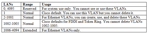
VLANs are referenced by number (0-4095). Because of historical reasons some VLAN numbers are considered to be Normal whereas some others are considered to be extended.
Both ISL and 802.1Q support extended-range VLANs. Originally ISL began life only supporting Normal range using 10bits of the 15bits reserved in ISL header to identify the VLAN ID. Later-defined 802.1q used a 12bit VLAN ID field means support 4096 VLANs (0-4095). As it was the Industry standard, Cisco extended the VLAN numbering as per 802.1q and this extension is known Extended VLAN.
Basically CISCO changed ISL to use 12bit of the 15bits in VLAN ID field , thereby supporting extended range.In NX-OS VLAN 3968-4094 is reserved for internal use in each VDC by default.
Something about Extended VLAN:
- We cannot create a VLAN in the extended range when the reduced MAC address feature is disabled.
- The VLAN database mode does not support extended VLAN configuration.
- Normal VLANs are stored in vlan.dat file as well NVRAM depending on VTP mode but extended VLANs configuration stored in NVRAM not in vlan.dat.
- Each routed port the switch creates an internal VLAN for its use. These internal VLANs use extended range VLAN number. If we try to create an extended VLAN with VLAN id that is already allocated as internal VLAN then an error message is generated and command is rejected.(config)#vlan internal allocation policy ascending(config)#vlan internal allocation policy descending
- In VTP version 1 and 2, if we want to create extended range VLAN then switch has to be in transparent mode. We can’t create extended VLAN if our switch is in serve or client mode. VTP version 3 supports extended VLANs in server and transparent mode.
6. Layer 2 Switchport can act as below:
- Access port
- Trunk Port
- Tunnel Port as known as QinQTunneling
Access Port: An access port can have only one VLAN configured on the interface and it can carry traffic for only one VLAN.
Trunk Port: An Trunk port can carry multiple VLANs Traffic VLANs simultaneously.
Or
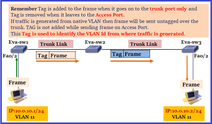
Trunking is mechanism that is used to pass multiple VLANs information between switches. Trunking is also known as tagging. Trunking status can be negotiated on a link using DTP. Let’s have a look how tag is added:
Two trunking protocols
- ISL
- Cisco proprietary
- All frames are encapsulated
- Adds 26-byte ISL header and 4 byte CRC to ethernet frame.
- Does not have a concept of Native VLAN. These days Cisco is also not using ISL.
- 802.1q
- An industry standard trunking method
- Insert Tag into Ethernet Frame, add 4byte of overhead means less overhead then ISL.
- Support Native VLAN and native VLAN is not tagged
- FCS is recalculated for the entire frame after the tag is inserted.
DTP (Dynamic Trunking Protocol)
- DTP is Cisco proprietary Protocol.
- DTP allows a switchport link to auto negotiates into either an access port or a trunk port based on the DTP negotiation and also used for negotiating the encapsulation type of either IEEE 802.1Q or Cisco ISL (Inter-Switch Link).
- By default DTP is enabled and the interfaces of your switches will be in “dynamic auto” or “dynamic desirable” mode depending on platform.
- DTP modes
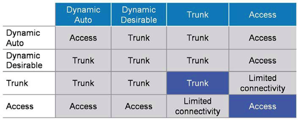
| Mode | Command | Purpose |
| Access | switchport mode access | Puts the interface into permanent non-trunking (access) Port and force to convert the link into a Access link and will never become trunk. Disable sending and processing DTP packets means deactivated DTP on Port. Remember there is no need to use the ‘switchport nonnegotiate’ command on access ports. |
| Trunk | Switchport mode trunk | Puts the interface into permanent trunking mode and force to convert the link into a trunk link.Sends DTP packets to attempt to negotiate a trunk on the other end. |
| Dynamic desirable | Switchport mode dynamic desirable | Interface will actively ask the other side to become Trunk means sends DTP packets to attempt to negotiate a trunk on the other end.If DTP negotiation fails then Port will become an Access Port. |
| Dynamic auto | Switchport mode dynamic auto | Interface will wait passively for the other side to ask to become a Trunk. If no one asks to become trunk then will become Access Port. |
| Nonegotiate | Switchport mode nonegotiate | Disable DTP on the Port. |
Please see the Below output of “show interface fax/y switchport” command.

| Administrative Trunking Encapsulation | Operational Trunking Encapsulation |
| Define what we have configured on particular port using “switchport trunk encapsulation” command.
There are three below possibilities A. ISL B. Dot1q C. Negotiate (Default): Encapsulation is negotiated to select either ISL or Dot1Q. If both end support both types than ISL is favored as DTP and ISL both are Cisco Proprietary :). |
Displays end result of Negotiation either ISL or Dot1q.
There are three below Possibilities. A. ISL B. Dot1q C. Native: end result of negotiation is not trunk or we can say end result of negotiation is Access port. |
Let’s discuss something about Limited connectivity.
We will not see limited connectivity in real environment but anyways let’s say we have two switches connected to each other as below:
As per topology one end is configured as access VLAN 10 and the other forced as Trunk, there will be limited connectivity.
In this case, only one VLAN (which is VLAN 10) can successfully communicate over the link, and require specific configuration, I mean DATA VLAN (VLAN 10) and Native VLAN has to match. Only VLAN 10 traffic will successfully traverse the link.
7. Native VLAN : Native VLAN is used to carry untagged traffic across trunk.
How Native VLAN work:
- Frame belonging to the native VLAN are not tagged when sent out on trunk.
- Frames received untagged on the trunk links are sent to the Native VLAN.
When switch receives an Ethernet frame without a tag on trunk, it will assume that it belongs to the native VLAN. For this reason we need to make sure that native VLAN is same on both side. IF spanning-tree detects a native VLAN mismatch, spanning-tree blocks “Local Native VLAN traffic and remote VLAN traffic on trunk however the trunk still remains up for other VLAN.
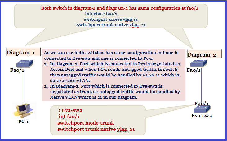
There are two methods to handle “untagged traffic” over a port and it depends on port is either Access port or Trunk Port.When we receive untagged traffic on Access Port then this untagged traffic is carried by Access VLAN in which port is configured. When we receive untagged traffic on Trunk Port then this untagged traffic is carried by Native VLAN in which port is configured.
Let’s have a look in below Topology where we have two diagram and results are different depending on port role:
8. Inter VLAN Routing:
Inter VLAN routing is a method which is used to route traffic from one VLAN to another. Devices within a VLAN can communicate with each other without using routing but devices in different VLANs require a Layer 3 device (which do routing) to communicate with one another.
There are two ways to do inter VLAN routing:
- Router on Stick
- SVI
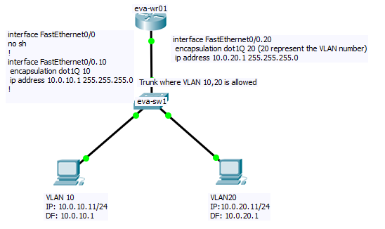
Router On Stick: When we use router for Inter-VLAN Communication than it’s known as router on stick.
Remember IP routing on a LAN sub-interface is only allowed if it is configured to work with trunking protocol (ISL or 802.1q) therefore we have to associate VLAN with each sub-interface. This association is used by router to decide where to send incoming traffic for further processing.
- Native VLAN must match at both side, If router receive untagged traffic then it will be processed by Interface which is configured as Native, if we haven’t configured Native manually then essentially traffic will land to physical Interface. While sending traffic router adds VLAN tag depending on Destination.
- encapsulation dot1q X command defines 802.1q encapsulation and sets the subinterface to VLAN X.
Question: what would happen if you did not define the native vlan on the router?
Ans. As we already discussed, when router receives untagged traffic then it will processed by interface which is configured as Native, if we haven’t configured Native VLAN manually then essentially traffic will land to physical Interface.
If we don’t define any of the sub-interfaces as native and don’t have an IP Address (means L3 traffic landing will fail) configured on the main physical interface, we will have no layer 3 traffic on the native VLAN. Maintenance and management traffic like CDP etc will still work because these are L2.
SVI (switched virtual interface):
SVI provides layer 3 processing of packets for all switchport associated with a VLAN. Remember VLAN is a Layer 2 concept. There is nothing like layer 3 VLAN but some guys thinks SVI as Layer 3 VLAN but it’s not correct. We should always use SVI not Layer 3 VLAN.

SVI interface does not come up until it is associated with a connected physical port and VLAN is available in L2 VLAN database.
Interview Question Related to above Topic
- Why we create VLAN?
- What is Native VLAN?
- How to we disable DTP negotiation?
- How to create a VLAN which is used by switch for internal use?
- How trunking works in below diagram.
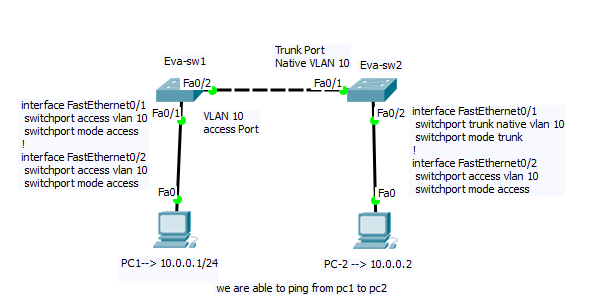
Can PC-1 communicate with PC-2 in below topology?
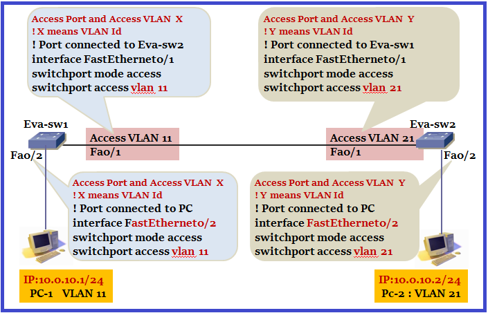
Notice that PC-1 is in VLAN 11 and PC-2 is in VLAN 21. Both have same Subnet. They both can ping each other. But aren’t the devices in different VLANs? They are, yet they can still communicate. Why is this?
Catch is, switch interlink … both ends are access port. An access port will not send tagged traffic. Hence when Eva-sw1 sends PC1’s traffic over the link, it will be untagged. When that packet comes into Eva-sw2’s fa0/1 interface, that interface is part of VLAN 21. Eva-sw2 will allow that frame to flow to PC2. The same will going to happen vice-versa.
I noticed one thing while doing this in real environment. Please see below logs for your reference.
TO be updated………………..
so question comes why Native VLAN mismatch on Access Port as Native VLAN is the concept of Trunk port.
But remember one thing always as discussed earlier.When we receive untagged traffic on Access Port then this untagged traffic is carried by Access VLAN in which port belongs.When we receive untagged traffic on Trunk Port then this untagged traffic is carried by Native VLAN in which port is configured. Here this message is showing untagged traffic handling is different at both ends. or we can think like whenever we configure a Port as Access Port or Port is negotiated as Access Port then Native VLAN will be the specific VLAN in which Port belongs.
Can PC-1 communicate with PC-2 in below topology?
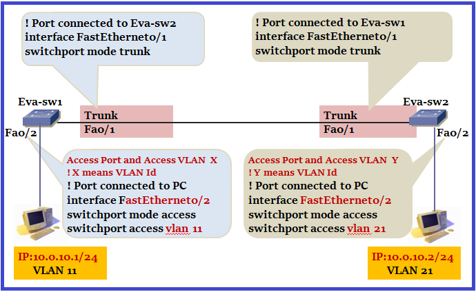
Let’s change inter link to Trunk and try the same. We are not able to ping now.
Let’s have a look in communication. When Eva-sw1 receives frame from PC then it sends PC1’s frame over the link with tag . Tag have information about the VLAN from which PC belongs in our example VLAN11. When it gets to Eva-sw2, it’ll look at that tag and ensure the frame is not sent out any access port that is not in VLAN 11. So communication will not happen.
Can PC-1 communicate with PC-2 in below topology?
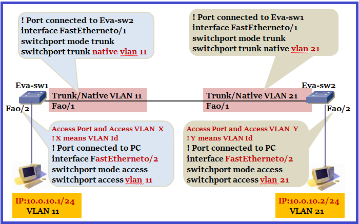
We learnt these two points when we went through the Native VLAN topic is below:
- Frame belonging to the native VLAN are not tagged when sent out on trunk.
- Frames received untagged on the trunk links are sent to the Native VLAN.
In real environment, we use the same native VLAN both sides of the trunk. But to understand native VLAN we designed like this. When Eva-sw1 receives traffic from PC-1 then eva-sw1 will send data untagged towards Eva-sw2. Why? Because PC-1 belongs from VLAN 11 which is Native VLAN in our design. When Eva-sw2 receives un-tagged frame then Eva-sw2 will send it to Native VLAN which is VLAN 21 in our design. Here the catch is we are leaking traffic from VLAN 11 to VLAN 21.
When I tried pinging from PC1 to PC2, it was not pinging even it is correct Theoretically. On digging a bit deeper I found STP is blocking communication. The BPDU’s still carry VLAN information with them.Logs which we will receive at switch are as below:
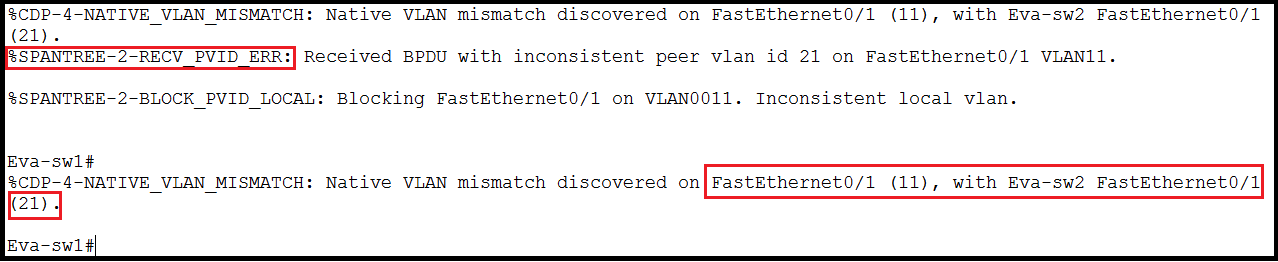
When i did “show spanning-tree vlan 11” below will be the output.
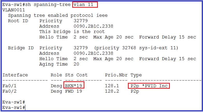
Port is showing in BKN state, the reason is STP inconsistency is detected on Connected port. We will discuss this later in STP session. When we disabled STP for VLAN 11 and 21 it’s started pinging but we can’t do The same in real environment. This is only for understanding the Native VLAN.
Private VLAN
Private-VLAN is the way in which we can divide a VLAN into sub-VLANs 0r sub-domains using a single IP subnet. There are two type of VLAN:-
- Primary VLAN: Original VLAN is working as primary VLAN and Primary VLAN is used to forward frames downstream to all Secondary VLANs.
- Secondary VLAN: Secondary VLANs are the sub-VLANs or sub-domains which belongs to Primary Private VLAN.
There are two types of secondary VLAN.
1. Isolated VLAN
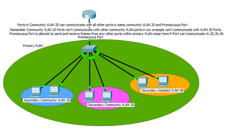
Port assigned to Isolated Secondary private VLAN can’t communicate with one another within Isolated VLAN but can communicate to Promiscuous port of Primary VLAN. Since isolated ports do not exchange frames with each other, we can use ONE isolated VLAN to connect all Isolated-Port to the Promiscuous-port.
2. Community VLAN
Port assigned to Community Secondary private VLAN can communicate with one another within same community VLAN and can forward frames upstream to the Promiscuous port of Primary VLAN.
There are two types of Ports:-
- Promiscuous Port
- Host Port (Isolated Port & Community Port)
Promiscuous Port
- Port which is allowed to send and receive frames from any other ports within VLAN.
- Usually connects to router, belongs to private VLAN.
Host Port
There are two type of host ports:
- Isolated Port
- Allowed to communicate only with ‘P-port’
- Belongs to an “Isolated secondary VLAN”.
2. Community Port
- Can communicate with ports in same community and P-port.
- Belongs to “Community secondary VLAN”
Practical steps:-
- Create Primary and Secondary VLAN and associate them with Private VLAN using following commands:-
| vlan 10 |
| private-vlan primary |
| vlan 20 |
| private-vlan community |
| vlan 30 |
| private-vlan community |
| vlan 40 |
| private-vlan isolated |
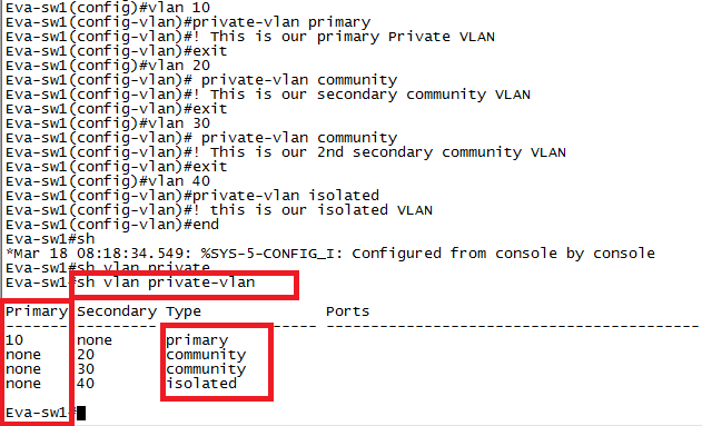
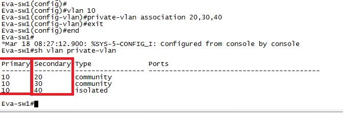
As per topology we have created one primary VLAN which is 10 and created three Secondary VLAN and associated with private VLAN community and isolated. Now associate all secondary VLAN with primary private VLAN using below command:
| vlan 10 |
| private-vlan association 20,30,40 |
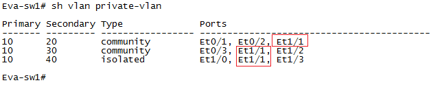
Check “show vlan private-vlan” and notice highlighted output.
 2. Configure Host Port and bind them to respective “isolated & community secondary VLAN.
| interface eth0/1
switchport mode private-vlan host switchport private-vlan host-association 10 20 ! VLAN 10 is our primary and 20 is our secondary so port is assigned to specific VLAN ! same way we can assign ports to other VLAN |
3. Create a “Promiscuous Port” and map (add) secondary VLANs for which traffic is received by Promiscuous Port.
interface Eth1/1
switchport mode private-vlan promiscuous
switchport private-vlan mapping 10 add 20,30,40
! 10 is our primary VLAN and we mapped all secondary VLAN 20,30,40
As per our topology port which is going to router is promiscuous port and see the show vlan private-vlan output where we can see this port (eth1/1) is showing in all VLAN.
Video
What is use of assign Native VLAN on router’s interface ?
Hi Shashank,
Thanks to reaching out to us!
I have updated your query on Router on stick topic. Hope I make you clear on your query.
Regards,
Evanetworkteam
Superb .
Very useful content & Easy to understand.