Categories
SwitchingAgenda
- What is STP and why do we use STP?
- How STP Works?
- STP Feature like Port fast , BPDU Guard, Root Guard
- Direct vs Indirect failure
1. STP is a layer 2 Protocol which is used to avoid loops and provide path Redundancy. STP is defined as IEEE 802.1D standard.
2. STP use messages (known as BPDUs) between switches to stabilize the network into a logical loop free topology.
3.By default STP is enabled for all active VLANs and all ports of switch.
Why Loop?
**if loop is created than following problem occurs:-
- Broadcast Storm
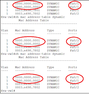
- Mac Address table Instability
- Multiple frame Transmission
The Layer 2 traffic can be classified as unicast, multicast, and broadcast. Broadcasts and Multicasts are required for the normal operation of the network. MAC addresses for broadcast and multicast are given below.
- Broadcast Destination MAC address – FF:FF:FF:FF:FF:FFF
- Multicast Destination MAC addresses – 01:00:5E:00:00:00 to 01:00:5E:7F:FF:FF
For broadcast and multicast traffic switch needs to forward the frame out all its ports.
How STP is works:-
- One Root Bridge per N/W or per VLAN
- One RP per Non-RB
- One DP per Segment
- Non-designated ports are unused/Blocked.
1st. Root Bridge Selection Process:-A switch which has Lower Bridge Id become RB. Bridge Id consist three things:-
- Bridge priority
- Extended system ID (Why this is used?
- Mac address

When the extended system ID is not enabled, STP uses one MAC address per VLAN to make the bridge ID unique for each VLAN. We can enable it by using “spanning-tree extend system-id” command. One important thing recent switches don’t allow this command to be removed even though it is displayed in the running-config and always use system ID extension.
If you have a network device in your network with the extended system ID enabled, you should also enable the extended system ID on all other Layer 2 connected network devices to avoid undesirable root bridge election and spanning tree topology issues.
2nd. Root Port Selection Process: – A forwarding port that is the best port from Non-RB to RB.
- Lowest Root Path Cost to Reach RB
- Lowest sender bridge id
- Lowest sender Port-ID [Port Priority + Port number]
- Lowest Local Port-ID [Port Priority + Port number]

To have better understanding please apply your logic in below topology.

Path cost and Port ID (Port Priority) can be used to influence the RP selection.
3rd. Designated Port selection Process:-A forwarding port is elected for every LAN segment. DP is responsible to forward BPDU and frame to that LAN segment.
- Lowest Root Path Cost to Reach RB
- Lowest sender bridge id
- Lowest sender Port-ID [Port Priority + Port number]
- Lowest Local Port-ID [Port Priority + Port number]
4th. All other ports go into Blocking Mode
| Show Spanning-tree vlan XXX detail
Focus on following thing
|
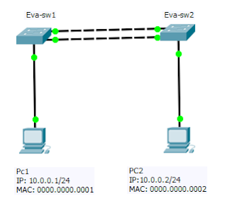
Let’s have a look in below topology

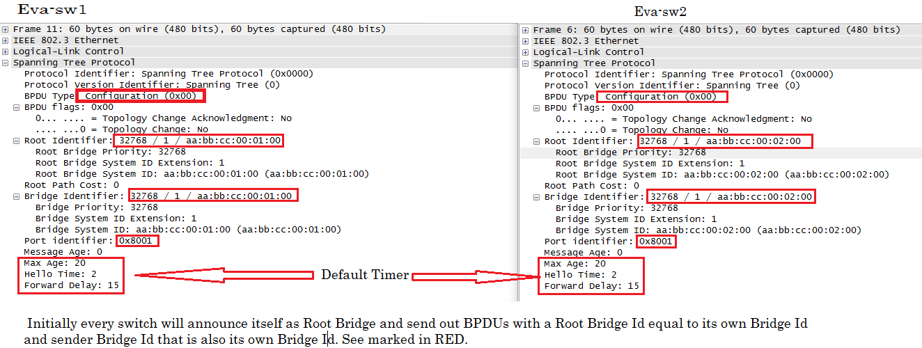
1. Initially every switch will announce itself as root bridge and send out BPDUs with a root bridge id equal to its own bridge id and sender bridge id that is also its own bridge id.
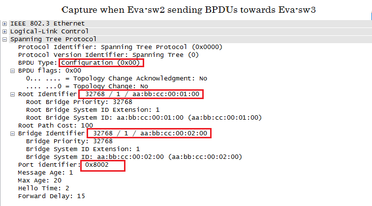
2. Once BPDUs are exchanged between switches they will do election based better bridge id and starts advertising this new Root bridge id in its BPDUs. Let’s see the capture
Let’s understand STP election process using below Topology:
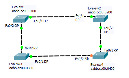
In above Diagram Eva-sw1 will be elected as RB.Why?
Because Eva-sw1 has lower bridge id as all switch has same priority but eva-sw1 has lower MAC address so it’s selected as Root Bridge as mention in root bridge election process. All port will be in forwarding state at RB.
RP election:
A. Fa0/2 at Eva-sw3 is selected as RP because lowest path cost to reach RB. Same way at Eva-sw2 fa0/1 will be selected as RP.
B. At SW4, we have two ways to reach RB with same Path cost via fa0/1 and fa0/2 means we have to go next tie breaker.
C. As we know next tie breaker is Sender bridge idfor RP election so as per topology sender bridge id is lower from fa0/1 so this port will selected as RP.
DP Election:
As per topology all ports at RB becomes DP but what about LAN segment between Eva-sw3 and Eva-sw4?
There should be one DP in that segment which is elected based on DP criteria and port at Eva-sw3 will become DP as lowest path cost from Eva-sw3 to reach RB.
STP state:-
Disabled:-
1. Don’t send/received BPDUs.
2. Mac address Table is not Updated.
3. Data frame is not forwarded
Blocking:-
1. Don’t send BPDU but receive the BPDU
2. Mac address Table is not Updated.
3. Data frame is not forwarded
Listening:–
1. Send/received BPDUs
2. Mac address Table is not Updated.
3. Data frame is not forwarded
4. Forward delay 15
Q. Why listening state in STP?
Ans. During Listening state Switches will make decisions on which port is Rootport and
which are DP ports.
Learning
1. Send/received BPDUs
2. Mac address Table is Updated.
3. Data frame is not forwarded.
4. Forward delay 15
Forwarding:-
1. Send/received BPDUs
2. Mac address Table is Updated.
3. Data frame is forwarded.
*** STP Port state transit: Blocking –> Listening — > Learning — > Forwarding
BPDU:
Bridge Protocol Data Units (BPDUs) are containing information regarding the Root ID, Bridge ID, and path cost etc.
A bridge sends a BPDU frame using the unique MAC address of the port itself as a source address, and a well-known destination address of the STP multicastaddress 01:80:C2:00:00:00(on Native VLAN to STP).Cisco switch send s PVST+ BPDU to STP MAC address 01-00-0c-cc-cc-cd. Non-cisco devices floods the BPDUs because destination MAC address is an unknown Multicast Address.
BPDU Format for STP
| Bytes | Field | |
| 2 | Protocol ID | Always 0. Future enhancements to the protocol might cause the Protocol ID values to increase. |
| 1 | Version | Always 0. Future enhancements to the protocol might cause the Version value to increase. |
| 1 | Message type | BPDU Type(configuration=00 ; TCN=80 |
| 1 | Flags | Used to handle changes in the active topology
LSB(least significant Bit)=TC flag MSB(Most Significant Bit)=TCA flag |
| 8 | Root ID | Bridge ID of Root |
| 4 | Cost of path | Cost to reach RB |
| 8 | Bridge ID | BPDU sending Bridge ID |
| 2 | Port ID | BPDU sending Bridge port ID |
| 2 | Message Age | Seconds since root originated the BPDU. |
| 2 | Max Age time | Maximum time that a BPDU is saved. |
| 2 | Hello Time | Time between periodic Configuration BPDUs. |
| 2 | Forward Delay | Time interval spends in each of the listening and learning |
There are two type of BPDU:
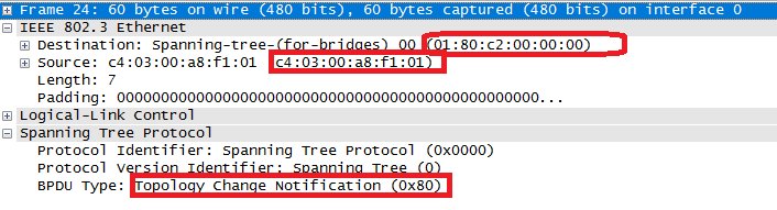
1. Configuration BPDU: – Generate by RB and used for spanning-tree calculation means it used to determine topology and stop/start forwarding at ports as required.
2. Topology Change Notification (TCN):-Topology change notification BPDU flows toward the RB to inform that active topology has been changed. TCN BPDU does not carry data about the change but informs recipients only that a change has occurred.

A. When a switch discovers topology change, it generates TCN BPDUand sends TCN on its root port. Upstream switch responds back to sender with TCA BPDU. In our topology TCN is generated by Eva-sw4 and TCA is sent by Eva-sw3.
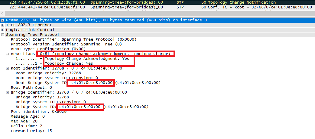
TCN/TCA:

C. Root sends a TCA back to sender and then sends a configuration BPDU with TC flag. This configuration BPDU with TC flag is received by every switch in the N/W to make them aware of N/W topology change and switches reduce their MAC aging time from default 300sec to forward delay value for the duration of the topology change. This causes recently idle entries to be flushed, entire VLAN.
Direct Failure Vs Indirect Failure:
The failure type is always taken from the perspective of a particular switch. Same failure will be either direct or indirect, depending on the switch’s relation to the failed link.
STA will handle failure as below:
1. Blocking Port: Nothing will happen, only expire information associated with failed port.
2. DP: Local switch does nothing. However downstream switch may detect loss of a root port and start reconverging.
3. RP: Information stored with RP is invalidated and will elect new RP based on stored info and found port will start transiting through listening.
A. Information stored with RP is invalidated and will elect new RP based on stored info and found port will start transiting through listening.

As discussed let’s assume Link3 went down mean there is direct failure for Eva-sw3 at blocking port means nothing will happen. Same there is direct failure for Eva-sw2 at Designated Port means local switch does nothing but don’t forget about TCN generation process i mean TCN process is remain same as we discuss earlier.
Let’s assume Link1 went down means there is direct failure for Eva-sw3 at Root Port so Eva-sw3 will invalidate the information stored with RP and check for new Root Port as Eva-sw3 are receiving BPDUs from Fa0/1 so fa0/1 will go throug the listening and learning state and it takes 30 secs to end up in forwarding state.
Indirect Failure
An indirect failure is not detected immediately and relies upon configuration BPDUs not being received for the duration of MAX_Age timer.
Let’s take the same example for understand it.

Whole story says we took 50sec (Max_Age + 2*Forward_Delay) to recover from Indirect failure.
Uplink Fast vs Backbone fast
- Uplink fast and backbone fast is Cisco proprietary feature.
- Uplink fast is used to detect direct failure whereas backbone fast is used to detect indirect failure.
- As we discussed direct failure takes 30 secs to end up in forwarding state and indirect failure takes 50sec to end up in forwarding state. So Cisco introduces these two features to minimize the recovery time from direct and indirect failures in network.
UplinkFast:
Uplink Fast is used when a direct root port failure should reconverge immediately by passing listening and learning state on blocking port. Means we are saving 30sec by using UplinkFast.
3. Remember that uplink fast cannot be configured on a ROOT switch. When we enable UplinkFast, it affects all VLANs on the switch. This feature not support on per VLAN basis and Per port Basis. We configure Uplinkfast on switch where we have blocking port.
BackboneFast
BackboneFast reduces the default convergence time in situations where the root port is lost and the backup link leads through a different switch. The convergence is reduced by 20sec from the default 50sec in such scenarios.
Let’s take same example of indirect failure.
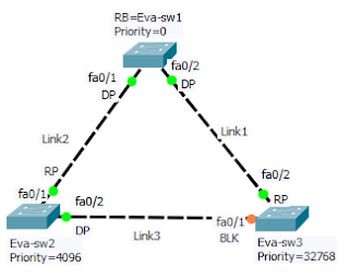
- When Link goes down, Eva-sw2 immediately detects the failure as its direct failure and assumes it is the root. It starts sending BPDUs to Eva-sw3 and claims to be the new root.
- As soon as Eva-sw3 receives the inferior BPDU from Eva-sw2, it starts to reconfirm its non-designated ports instead of waiting max_age. It sends a RLQ query on its root port for root bridge Eva-sw1.
- Root bridge Eva-sw1 receives the query and immediately answers with a RLQ response that specifies RB is alive. Once Eva-sw3 receives RLQ response means come to know it still has connectivity to the root bride. Eva-sw3 can then age out immediately the information stored on port Fa0/1. Fa0/1 transitions to listening and starts to send BPDUs. Means by passed Max_Age timer and saved 20sec.
- Eva-sw2 receives the better BPDU from Eva-sw3 and considers now the ports that lead to Eva-sw3 as its root port.
STP Features
Portfast:-
- Port immediately moves into Forwarding state, bypassing the listening and learning state.
- Portfast enabled port is also known as Edge port, term can be used interchangeably.
- Remember that by default spanning tree sends BPDUs from all ports regardless of whether PortFast is enabled or not.
Where do we enable Portfast?
we enable Portfast on user facing port where we are not suppose to receive BPDUs as end users are connected.
We can enable Portfast at global level as well interface level.
Why do you want to enable PortFast?
The PortFast feature is introduced to avoid network connectivity issues. Few applications like DHCP need to connect to the network immediately, else they will timeout. So if we are using PortFast means Port will come up immediately
without relying on forwardd delay and there will not be timeout for such kind of Applications.
Note:-
If Portfast enable interface receive BPDUs then come out from Portfast Status and act as normal STP port until it goes down and comes back up. Remember one thing Portfast doesn’t disable STP. Portfast enabled port sends BPDUs and participates in STP.
Advantage:-
- Minimize the unknown UnicastFlooding.
- Don’t generate TCN (CAM table is not “flush out”).
Commands
- Spanning-tree Portfast Default(This global level command, enable Portfast at all Access Port on switch.)
- Spanning-tree Portfast: – this is interface level command enable Portfast on that access port only.
- Spanning-tree Portfast Trunk : This is interface level command enable port fast on that trunk port.
Why this command as trunk is usually connected to another switch??
This command is designed for servers which are running 802.1q on their NICs and carrying multiple VLANs over them and port is configured as trunk.
- Show spanning-tree int fax/y portfast
- Show spanning-tree int fax/y detail
BPDUFilter
- BPDU filter is used to filter “sending or Receiving” BPDU on Switchport.
- if we enable BPDU guard on same interface as bpdufiltering, BPDUGuard has no effect because BPDUFilter take precedence over BPDU Guard.
Where do we enable BPDUFilter?
It is extremely useful on those switchport (user facing) which are configured as Portfast and there is no need of send or receive BPDUs. We can enable it at global level as well interface level but it works differently.
Why do we need BPDUFilter?
We can use bpdufilter when we want to add a new switch for emergency into our network but we don’t want it to participating in spanning tree. Please do remember bpdufilter disable the STP so be careful while using this feature.
We may run into Loop if we are connecting multiple port to same switch with bpdufilter.
| Global Level | Interface level |
| When we enable at globally than it filter out -bound BPDUs (means prevent sending of BPDUs). The interfaces still send some BPDUs(11) at the link-up, if a BPDU is received, the interface loses its Port Fast status and port become normal STP port and BPDU Filtering is disabled until port goes down and comes back.
spanning-tree portfast bpdufilter default |
The interface doesn’t send any BPDU and ignores the received ones. This basically disables spanning-tree on the interface, so use it carefully.
spanning-tree bpdufilter enable |
BPDU Guard
- BPDU guard prevents a port from receiving BPDUs or from being connected to unauthorized switches or accidental connection to switching devices.
- When BPDU Guard enable port receives BPDUs, Port will be moved in “err-disabled” State.
Where do we enable BPDU Guard?
we enable BPDU Guard on user facing port where we are not suppose to receive BPDUs as end users are connected.
We can enable it at global level as well interface level. Please see below.
| Global Level | Interface Level |
| “spanning-tree portfast bpduguard default” –> Activates the BPDUGuard only on Ports that operates in portfast state. if BPDUGuard enabled port receive BPDU the it moves to err-disabled state. Portfast will not be disabled but port will go in err-disable first. | “spanning-tree bpduguard enable” Activates the BPDUGuard on port regardless Portfast status. If BPDUGuard enabled port receive BPDU then it moves to err-disabled state, regardless of the Port Fast status. |
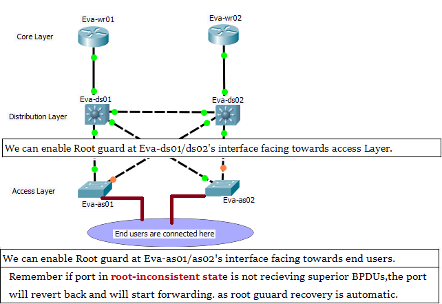
Root Guard
- Root guard prevents an unauthorized switch from becoming RB.
- If this Root Guard enable port recieve BPDU with:
- higher bridge id then port act as normal STP Port means no action is taken by root guard.
- lower Bridge then port move into “Root inconsistent” state.
** Root Guard enable port can forward and relay bpdu’s but can’t become Root. Enable switch port that we don’t want to be root.
**Root guard can be at interface level using spanning-tree guard root
Where we enable the Root Guard feature?
Normal mode (enable) – Port is allowed to continue its operation merely marks the port as being in undetermined state and generates a syslog message.
Awesome one.. we have small pack of big information… Thank you so much for making such a good document. Can you please let me know can we have applied packet capture on Packet tracer ??
Thanks for documents. Awesome document’s.
Very well explained
Thank you very much ,this is very helpful , cheers
Great Content & Very well Explained.
thanks its clear to understand
Perfect one to understand the STP in detailed.
Thanks, I’ve been looking for details about this subject for ages and yours is the best I have discovered so far.