Categories
StudyAgenda
- Introduction of OSPF and how OSPF works.
- What is Area and Advantage of Area?
- OSPF Neighbor Table and database table and Routing Table.
- OSPF Packet Type
- OSPF Neighbors
- LSA Header and Types
- DR (Designated Router)/BDR (Backup Designated Router)
- Special Area Type
- OSPF Authentication
- OSPF is a “Open standard” routing protocol.
- OSPF is a “Link state” routing Protocol which uses shortest path first(SPF) or Djikstra algorithm to determine the shortest Path.
- OSPF is a “Classless” Routing Protocol means support VLSM /CIDR /Discontigiuous N/W.
- OSPF uses “Area” concept for scalability.
- OSPF uses metric as COST which is equal to Reference bandwidthh/Link bandwidth and by default (10^8 /BW in bps).
- OSPF uses IP protocol 89 as its transport means OSPF packets travel as the payload of their IP packets. IP packets contain a protocol field (89) which informs the receiving routers that it contains OSFP data.There are 5 types of OSPF packets like Hello, DBD, LSR, LSU, and LSAck.
- OSPF supports authentication (Null,Clear text, MD5).
- OSPF uses both unicast and multicast{224.0.0.5 (ALLSPFRouters) and 224.0.0.6} to send ospf packets.
- Default administrative distance for OSPF is 110.
- OSPF uses Router-Id to uniquely identify the router in OSPF domain and Router-Id is 32bit address which is selected using below criteria:
1. Manually configured.
2. Highest IP address on a loopback interface.
3. Highest IP address on a non-loopback interface.
How OSPF works?
OSPF uses a link state logic where OSPF router does following generic process:
A. Neighbor Discovery: Each router discover its neighbor by sending hello messages and forms adjacencies with its neighbors.
B. Exchange Link State Advertisement and build the Topology Database: Each router generates its own LSA (LSA contains the state and cost of each directly connected link). OSPF routers flood to their LSAs to adjacent. Adjacent stores a LSA copy on its database and flood the LSA to other directly connected router means process continuous until all router in the area have all LSAs.
C. Execute the SPF algo and build the routing Table: Routers execute the SPF algo and choose the best route for each destination as per SPF tree and insert route into the routing table.
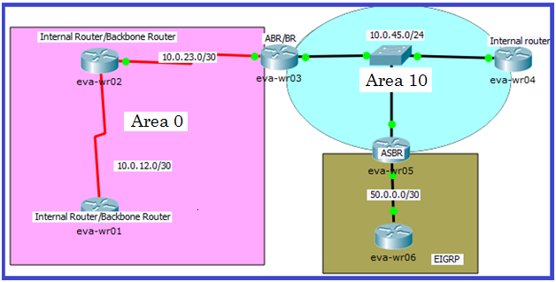
Area: group of routers that share common link state information. This is accomplished by routers, flooding their individual link states to all other routers in the area.
If we have single area then area id is doesn’t matter but if we have multiple area then first area must be area 0 and all non-backbone area must be directly connected to area 0.
Q. Why all non-backbone area must be directly connected to Area 0.
Ans. OSPF use link state principle only within Area. OSPF acts as a distance vector protocol between areas so OSPF uses a Backbone area (area 0) to exchange routes between other areas without creating routing loops because of distance vector behaviour.
Now to make it simple we can think like if each OSPF area is a router running RIP and recall how loop may occur in RIP will get our answer as well 🙂. So this rule is made by OSPF to prevent loops, and to make more efficient the routing update processes.
Advantage of area:
1. Minimize routing Table
2. Localize impact of topology change within Area
3. Detailed LSA flooding stops at the Area boundary
** SPF is not recalculated if topology change is in another area.
**ABR doesn’t announce topological information b/w area instead only routing information is injected into other area.
**OSPF use link state principle only within Area but OSPF distributes inter-area topology information using distance vector method.
show ip ospf
show ip ospf database
OSPF maintains three Tables:
1. Neighbor Table: list of Neighbor
2. Topology Table:
- Identical LSDB for routers within Area.
- Contains all routers and their attached links information in a Area.
- Each router has full picture of topology
Neighbor Requirement:
- Interface Area-Id must be same.
- Hello and Dead Interval must be same.
- Must pass Authentication ( if configured)
- Stub Area flags match.
- Interface Network must be same.
- Network type must be same.
- Interface MTU size must be match.
*** General rules to become neighbor:-
1st .Check Neighbor requirement (must match).
2nd. either election happen or not (if election happened than right router should be DR)
3rd. Neighbor is automatically discovered or manually configured.
3. Routing Table: Routing Table has list of best paths to the destination.
OSPF Router Types:
There are four types of OSPF routers which are determined by a router’s function and/or location within an OSPF area:
1. Internal Router (IR) – A router that has all of its interfaces within the same area is called an IR.
2. Backbone Router (BR)– A router that has at least one OSPF interface within the area 0 (backbone area) is known as Backbone Router.
3. Area Border Router (ABR) – A router that has interfaces in two or more areas is known as ABR. An ABR always has atleast one interface that belongs to the backbone area. ABR maintains a separate Link state database for each of its connected areas.We would see Type3 and type 4 LSA’s from an ABR.
4. Autonomous System Boundary Router (ASBR) – an OSPF router that performs route injection (redistribution) from another route source (RIP, EIGRP etc.).
OSPF Path Type:
1. Intra-Area Routes: Intra area routes are routes that are originated and learned in the same area. We can identify the intra area route as “O” in the routing table.
2. Inter-Area Routes: Inter area routes are routes that are originated in some other OSPF area and are advertised into our area. We can identify the intra area route as “OIA” in the routing table.
3. External Routes: routes that are originated from other routing domain. E1 routes (when route comes as E1 means internal+external metric will be consideration). E2 Routes(by default external routes comes as E2 routes and E2 means External Metric only will be consideration).
How OSPF install best route in routing table?
Ans:
I. When there are multiple routes available to the same network with different route types, routers use this order of preference (from highest to lowest):
1. Intra-area routes.
2. Inter-area routes.
3. External Type-1 routes.
4. External Type-2 routes.
II. If there are multiple routes to a network with the same route type, the OSPF metric calculated as cost based on the bandwidth is used for selecting the best route. The route with the lowest value for cost is chosen as the best route.
III. If there are multiple routes to a network with the same route type and cost, it chooses all the routes to be installed in the routing table, and the router does equal cost load balancing across multiple paths.
OSPF packets types:
| OSPF Packet | Type Code | Identify OSPF Packet Type as below | ||
| Version | Type | Packet Length | 1 | Hello |
| Router Id | 2 | Database Description | ||
| Checksum | AuType | 3 | Link State Request | |
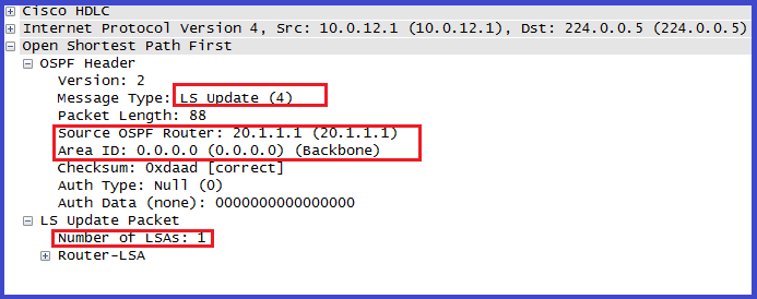
| Authentication Data | 4 | Link state Update | ||
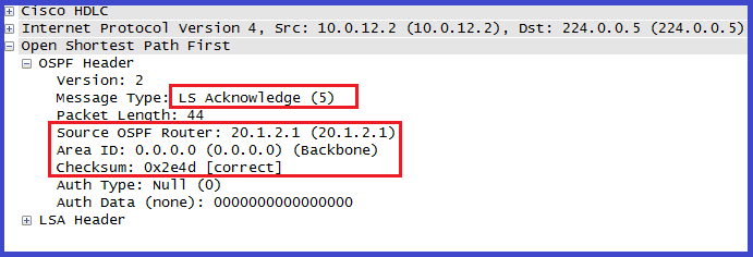
| OSPF Packet Data | 5 | Link State Acknowledgement | ||
| if AuType is 2 then authentication field is : | Router Id:is a 32-bit address that uniquely identifies the router in ospf domain. | |||
| 0x0000 | Key Id | Authentication Data Length | ||
| Cryptographic Sequence Number | https://www.ietf.org/rfc/rfc2328.txt | |||
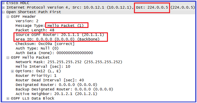
1. Hello: The hello message will perform below major functions such as:
1. Hello packets are used for neighbor discovery.
2. Maintain neighbor relationship by sending Hello at a given interval to ensure the neighbouring devices is still alive means act as Keepalive.
3. Check config parameters to become Neighbor like Area id, authentication, stub area flag, Network type.
2. Database Description: Contains a summary of the LSDB.
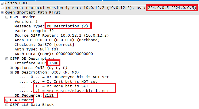
Something about header as below:
I-bit, or Initial bit, is set to 1 when the packet is the initial packet in series of DD packets. Subsequent DD packets have I-bit = 0.
M-bit, or More bit, is set to 1 to indicate that the packet is not the last in a series of DD packets. The last DD packet has M-bit = 0.
MS-bit, or Master/Slave bit, is set to 1 to indicate that the originator is the master (that is, is in control of the polling process) during a database synchronization. The slave has MS-bit = 0.
DD Sequence Number ensures that the full sequence of DD packets is received in the database synchronization process. The sequence number is set by the master to some unique value in the first DD packet, and the sequence is incremented in subsequent packets.
LSA Headers list some or all of the headers of the LSAs in the originator’s link-state database.
3. LSR: Requests specific link-state records from an OSPF neighbor.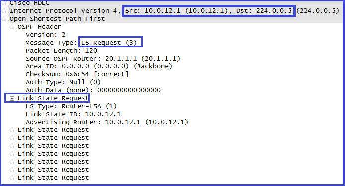
4. LSU: Sends specific link-state records that were requested.
5. LSAck: OSPF is a reliable protocol so we have a packet to acknowledge the others.
OSPF Neighbors: An OSPF adjacency is established in four general phase.
A. Neighbor Discovery
B. Bi-direction Communication
C. Database Syncronization
D. Full Adjacency
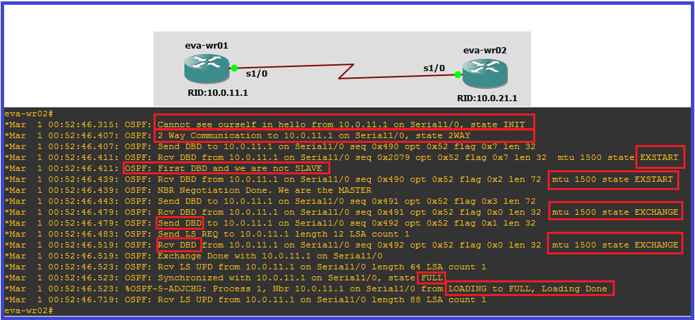
OSPF routers go through the below states while building neighborship with other routers.
1. Down: This is the first OSPF neighbor state, it means that no hellos have been received from neighbor, but hello packets can still be sent to the neighbor in this state.
Down means either no OSPF neighbors detected at this moment or detected neighbor is no more active.
2. Init: The Init state is reached when an OSPF router receives a hello packet but the local router ID is not listed in the received Neighbor field. This means that bidirectional communication has not been established between the peers. In this state, the router will record all neighbor router IDs and start including them in Hellos sent to the neighbors.
3. Attempt: The Attempt state is valid only for Non-Broadcast Multi-Access (NBMA) networks. It means that a hello packet has not been received from the neighbor and the local router is going to send a unicast hello packet to that neighbor within the specified hello interval period.
4. 2-Way: The 2-Way state indicates that the local router has received a hello packet with its own router ID in the Neighbor field. This means that bidirectional communication with the neighbor has been established.
If the link we are using is a multi-access network OSPF has to elect a DR (Designated Router) and BDR (Backup Designated Router) which optimize the exchange of information in broadcast segments.
5. ExStart: Master/salve election will happen. The router with the higher router ID becomes the master and starts the exchange. Master is the only router that can increment the sequence number of DBD packets in next stage.
6. Exchange: In the Exchange state, the local router and its neighbor exchange DBD packets that describe their local databases.
7. Loading: In this state, the actual exchange of link state information occurs.Based on the information provided by the DBDs, routers send LSR packets. The neighbor then provides the requested link-state information in LSU packets.
8. Full: In this state, routers are fully adjacent with each other. All the router and network LSAs are exchanged and the routers’ databases are fully synchronized.
LSA Header and Types:
| Age | Options | Type |
| Link State Id | ||
| Advertising Router | ||
| Sequence Number | ||
| Checksum Length | Length | |
| Type is the LSA type. | ||
| Advertising Router is router id of router that originated the LSA. | ||
| Seq Number is increamented every time a new instance of LSA is originated, so that other router can identify the most recent LSA. | ||
| https://www.ietf.org/rfc/rfc2328.txt | ||
1st. Router LSA:

A. Router LSA is generated by each router.
B. Information (list) about all of router’s links or interface, state and outgoing “Cost” of each link and any known OSPF neighbor’s on links.
C. Flooded within single Area.
D. Identify by router-Id of originating router.
E. Link-id is equal to router-Id.
F. Router LSA advertises “Host routes as Stub Networks”.
G. Link Type:-describe the general type of connection link provides.
| Link Type | Description |
| 1 | Point-to-point connection to other router |
| 2 | Connection to a transit N/W |
| 3 | Connection to a Stub N/W |
| 4 | Virtual Link |
Link Id:-identifies the object to which the link connects .this is depends on link type:-
| Link Type | Value of Link Id |
| 1 | Neighboring router’s router-Id |
| 2 | IP address of DR interface |
| 3 | Subnet address |
| 4 | Router-Id of Neighbor |
*** V bit in Flag indicates whether the advertising router is an endpoint of a virtual link. E bit in Flag. indicates whether the advertising router is an ASBR. B bit in flag, indicates whether the advertising router is an ABR.
2nd. Network LSA (Type 2):
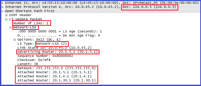
A. Generated by DR
B. DR represents multi-access N/W and all attached router as single virtual router.
C. Network LSA lists all attached router including DR itself .
D. Flooded within Area.
E. Link Id is IP address of DR interface.
F. Attached Router: – router-Id of all routers on the segment that fully adjacent with DR and router-Id of DR itself.
“sh ip ospf database Network”
3rd. Summary LSA:
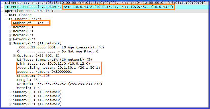
A. Sent into a single area to advertise destination outside that Area.
B. Link id is equal to N/W id of other Areas.
C. By default routes are not summarized. If you are using manual summarization than only intra-area routes are summarized.
D. Generated by ABR and regenerated by sub-sequent ABR. ABR only accepts and process Type 3 LSA received from Backbone Area. Remember one thing if type 3 LSA received from Non-Backbone area then ignore it.
E. When an ABR originates a N/W summary LSA, it includes the cost from itself to the destination the LSA is advertising.
4th .Summary LSA (ASBR):
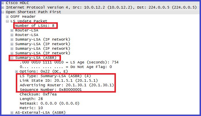
A. Generated by ABR and regenerated by sub-sequent ABR
B. Describe routes to ASBR.
C. Link Id is equal to ASBR router-Id.
D. When two ASBR are announcing E2 route with same metric then type 4 LSA is useful for deciding which ASBR is closer.
5th. Type 5(External LSA)
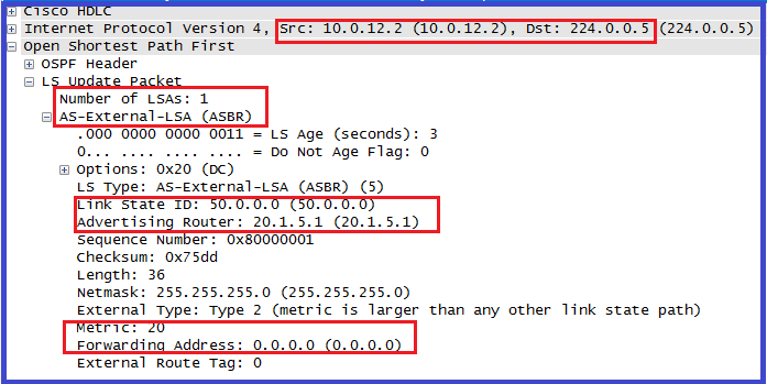
A. Generated by ASBR
B. Type 5 LSA describes routes to N/W which are outside the AS.
C. Link Id is equal to N/w Id.
D. If “E” bit set to 1, the metric type is E2 but if “E” bit is set to 0 then metric type is E1.
E. Forwarding Address(think):-address to which packets for advertised destination should be forward.( If 0.0.0.0 means to ASBR)
OSPF Area Type:
OSPF defines multiple area types, depending on what LSAs are permitted to be flooded and generated inside area.
As we already discussed OSPF prevents loop by using backbone area concept and all the non-backbone areas must be directly connected to the Backbone area.
There are many Non-Backbone OSPF Area types. These are; Normal Area, Stub, Totally Stub, NSSA and Totally NSSA Areas.
1. Normal Area: Normal OSPF areas allow all the LSA Types into the Area.
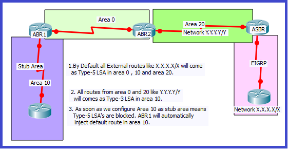
2. Stub Area:
A. Block type 5 LSA (or type 4) means there is no “OE1 or OE2” routes.
B. ABR automatic generate “default route” as type 3 LSA means we are replacing Type 5 LSA as default route so stub area routes can connect to external routes.
C. Improved performance by reducing size of LSDB along with routing Table.
D. A stub area can’t be transit Area for Virtual link but tunnel can be used instead.
E. Backbone Area can’t be configured as Stub Area.
F. ASBR must not be in stub Area.
G. Default cost=1 but you can change using [area area-id default-cost XX] command.
What happen if an area has Two ABR?
Configuration: – area area-id stub (means in Hello (option=8) E=0(within Stub area); they will not accepts any hello from router which E (E=1 is for all external LSA) bit set 1. So this command is for all router in Area.
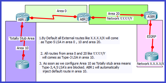
3. Totally Stub:
A. Cisco Proprietary feature.
B. Block type 3, 4, 5 LSAs means there is no “OIA, OE1 or OE2” routes in RT.
C. ABR automatic generate “default route” as type 3 LSA means Type 3,4,5 is replaced as single type 3 LSA that is default route.
Configuration: Same command as stub Area but at ABR use [Area area-Id no-summary] command
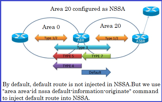
4. NSSA:
A. Stub area with ASBR.
B. Generate Type 7 LSA which is converted into type 5 when ABR receive.
C. Type 5 LSA is blocked.
D. ABR doesn’t generate default route but we can use (area area-id nssa default-information-originate) command for default route.
E. No OE1 or OE2 routes but ON1 or ON2 is there.
How it is useful?
[Area area-id NSSA] means P bit=1 when ABR receive Type 7 LSA with P=1 then translate to type 5 but P=0 then don’t translate.
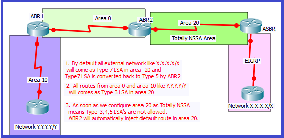
5. Totally NSSA:-
A. Block type 3, 4, 5 LSA means there is no “OIA, OE1 or OE2” routes in RT but have ON1 or ON2 routes.
B. Default route is automatically generated by ABR.
C. (Area area-id Nssa no-summary) command at ABR.
DR/BDR:
OSPF uses a DR in a particular subnet for two main purposes:
1. To manage the flooding process on the multi-access Network.
2. To represent the multi-access network and its attached router to the rest of the OSPF area.
Basically so we can say DR is used to minimize OSPF adjacencies {n(n-1)/2 , where n is number of routers} and LSA replication.
1. DR(Designated Router): DR is a router that receives LSA from neighbor in the segment and sends to the other neighbor.
Please keep in mind that a router might be a DR/BDR on one of its attached multi-access networks, and it might not be the DR/BDR on another of its attached multi-access networks. So we can say the DR/BDR is a property of a router’s interface, not the entire router.
2. BDR (Backup Designated Router):- used for redundancy of DR.
3. DRothers:
A. Neither DR nor BDR means all other routers on link.
B. Form full neighbor-ship with DR & BDR and two-way with other routers.
DR/BDR Election :
1. Router Priority
2. Highest Router-Id
** If priority is set to “0” means don’t participate in DR/BDR election.
We can change the priority if we like by using the ip ospf priority command.The default priority is 1.we need to use “clear ip ospf process” before this change takes effect.
DR & BDR Election Process:
Step 1 . When an interface first becomes active on a multi-access network it sets the DR/BDR to 0.0.0.0 and sets a wait timer which is equal to deal interval and router starts ospf process and listen for ospf hellos and see who else is out there. if a DR/BDR exist router, accepts them.
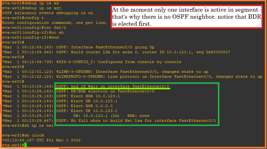
step 2 . If there is no BDR then router with the highest ospf priority is elected as BDR (if there is tie then Router-id used as tie breaker). If there is no active DR then this BDR router is promoted to DR and new election process begin again for BDR.
Please do remember once DR/BDR is elected then election do not take place again unless the DR or BDR are lost.
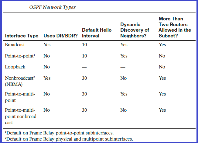
OSPF Network Type:
OSPF’s functionality is different across several different network topology Types.
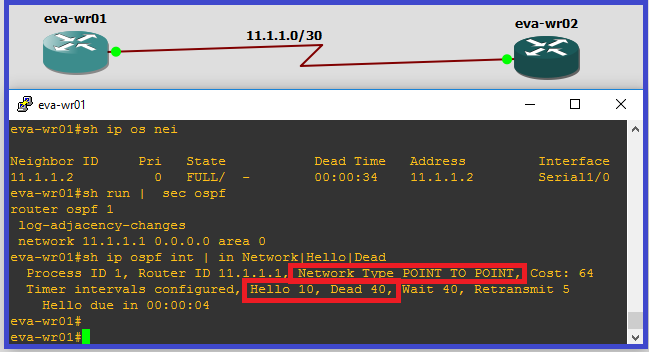
1. Point to Point Network:
- A network where two routers are directly connected. Like T1 Point-to-point connection, framerelay and atm point-to-point subinterfaces or other point-to-point links.
- No DR/BDR election.
- Default timers: hello interval 10, dead interval 40.
- Discover neighbor automatically.
- OSPF packets will be sent as multicast packets (224.0.0.5).
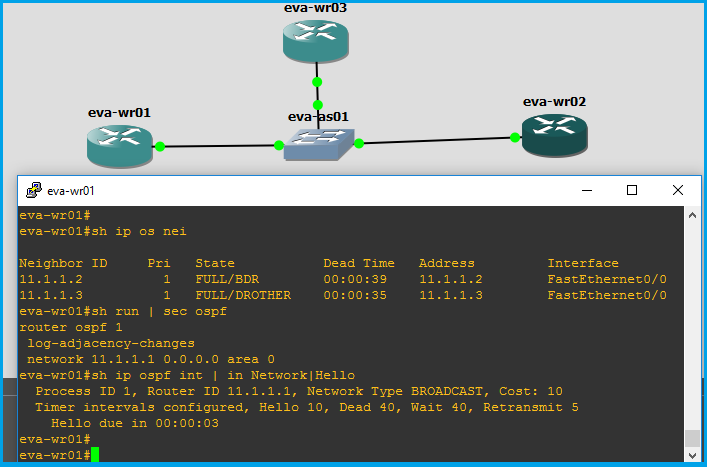
2. Broadcast Network:
- A multi-access broadcast network such as Ethernet, Tokenring, and FDDI.
- DR/BDR election happens.
- Default timers: hello interval 10, dead interval 40.
- Discover neighbor automatically.
- OSPF Packets to DRs and BDRs is multicast to 224.0.0.6 and OSPF Packet from DRs and BDRs to other routers is multicast to 224.0.0.5.
3. Nonbroadcast Multiaccess (NBMA):
- A network where one interface can connect to multiple routers but does not have broadcast capability. Frame-relay, ATM and X.25 Are examples of NBMA.
- DR/BDR election happens.
- Default timers: hello interval 30, dead interval 120.
- Neighbor must be manually configured means OSPF uses unicast instead of multicast packets.
- There are five modes of OSPF operatioin available for NBMA Networks as below:
A. RFC compliant modes:
- Nonbroadcast
- Point to multipoint
B. CISCO proprietary Mode:
- Broadcast
- Point to point
- Point to multipoint non-broadcast
Point-To-Multipoint is usually a link with more than 2 routers on it and In Point-to-multipoint mdoe treat each adjacent neighbor as a point-to-point connection in the SPT . Used when VCs does support multicast and broadcast. Point-to-Multipoint Nonbroadcast Mode is CISCO specific Feature same as Point-to-Multipoint but it is useful when Multicast and broadcast is not enabled on VCs as using unicast packet instead of multicast Packets.
Virtual Link:
As we already discuss that all areas must be connected to the backbone area 0,however it may be difficult for some reason to physically connect an area to the backbone; in such cases we will have to provide a logical connection to the backbone to temporarily solve the problem.
There are two ways to provide logical connection to the backbone area.
1. Virtual Link
2. GRE tunnel
Virtual Link:
A. Virtual links are used to connect discontigiuous area to Backbone area.
B. Area through which the virtual link is configured known as transit area must have full routing information.
C. Virtual link must be establish b/w two router (ABRs) that share a common Area and one of them must be connected to the Backbone Area.
D. Router use DNA (don’t age) bit so periodic re-flooding (30min) will not occurs over this virtual link.
| Virtual Link | GRE Tunnel |
| Only routing updates are tunneled into the virtual-link, but data traffic is not. | Both routing updates and data traffic are tunneled; this introduces more overhead. |
| Transit area can’t be a stub area. | The tunnel can go through a stubarea. |
I want to to thank you for this great read!! I absolutely enjoyed every bit of it.
I have got you saved as a favorite to look at
new things you post…
Thanks to you for deep knowledge sharing on OSPF. Kindly also include OSPF Route and LSA filtering.